Control device of continuously variable transmission for vehicle

a technology of control device and transmission device, which is applied in the direction of mechanical equipment, hoisting equipment, instruments, etc., can solve the problems of unfavorable acceleration performance (start performance) at the restart, the return of the gear ratio, and the belt return cannot be guaranteed

Active Publication Date: 2014-08-05
TOYOTA JIDOSHA KK
View PDF13 Cites 14 Cited by
  • Summary
  • Abstract
  • Description
  • Claims
  • Application Information

AI Technical Summary

Benefits of technology

[0009]To achieve the object, the present invention provides (a) a control device of a continuously variable transmission for a vehicle having a pair of variable pulleys with variable effective diameters of an input-side variable pulley and an output-side variable pulley and a transmission belt wrapped around between the pair of the variable pulleys, the continuously variable transmission respectively controlling an input-side thrust force of the input-side variable pulley and an output-side thrust force of the output-side variable pulley to set an actual gear ratio to a target gear ratio and preventing a slip of the transmission belt, the continuously variable transmission having a lowest-speed-side gear ratio determined by mechanically preventing movement of an input-side rotating body moved in an axial direction for varying an effective diameter of the input-side variable pulley, (b) the control device differentiating control methods of the input-side thrust force and the output-side thrust force based on whether the actual gear ratio is already the lowest-speed-side gear ratio if it is determined that a detection value of a rotation speed for calculating the actual gear ratio does not reflect an actual rotation speed.
[0011]Preferably, if the actual gear ratio is already the lowest-speed-side gear ratio, a target input-side thrust force and a target output-side thrust force are set to be thrust forces for maintaining the lowest-speed-side gear ratio and preventing a slip of the transmission belt, and wherein the target input-side thrust force is made lower by a predetermined value. Consequently, for example, the control can be provided such that a slip of the transmission belt is prevented from occurring while maintaining the lowest-speed-side gear ratio. Since the input-side pulley pressure in the input-side variable pulley can be reduced, the fuel efficiency improving effect can be acquired. In other words, if it is known that the actual gear ratio is the lowest-speed-side gear ratio, the input-side movable rotating body is mechanically prevented from moving (is abutting on a hardware limit) and the reduction of the input-side pulley pressure from the pulley pressure for maintaining the lowest-speed-side gear ratio does not move the input-side movable rotating body and does not reduce the belt clamping pressure any more. Therefore, even if the target input-side thrust force is made lower by a predetermined value, the lowest-speed-side gear ratio can be maintained while a slip of the transmission belt is prevented.
[0014]Preferably, the control methods of the input-side thrust force and the output-side thrust force are differentiated during vehicle deceleration running when the gear ratio is controlled toward the lowest-speed-side gear ratio. Consequently, the actual gear ratio can be retained at the lowest-speed-side gear ratio without causing a belt slip of the continuously variable transmission for a vehicle during vehicle stop and during extremely-low-speed running, for example. Therefore, the vehicle restart performance during vehicle stop and the reacceleration performance during low-speed running are properly ensured.
[0015]Preferably, a detection value of the rotation speed is within a rotation speed range less than an extremely low rotation speed obtained in advance as a rotation speed range in which the reliability of the detection value is reduced, it is determined that the detection value of the rotation speed does not reflect an actual rotation speed. Consequently, the actual gear ratio can be retained at the lowest-speed-side gear ratio without causing a belt slip of the continuously variable transmission for a vehicle during vehicle stop and during extremely-low-speed running, for example. Therefore, the vehicle restart performance during vehicle stop and the reacceleration performance during low-speed running are properly ensured.

Problems solved by technology

However, the technique proposed by Patent Document 1 does not assure a belt return, i.e., a return of the gear ratio to the lowest-speed-side gear ratio.
Since input torque is limited, i.e., the torque is lowered at the restart of a vehicle, the acceleration performance (start performance) at the restart is not certainly ensured.
However, in this case, although the lowest-speed-side gear ratio can be achieved, because the primary thrust force and the secondary thrust force are made higher than necessary, the pulley pressures are always made higher during low-speed running and during vehicle stop and, therefore, fuel efficiency may be reduced.
The problems described above are not well-known and no proposal has hitherto been made on retaining the gear ratio to the lowest-speed-side gear ratio without causing a belt slip regardless of whether a gear ratio is returned to the lowest-speed-side gear ratio during the running state in which a detection value of a rotation speed reflects the actual rotation speed.

Method used


Image

  • Control device of continuously variable transmission for vehicle
  • Control device of continuously variable transmission for vehicle
  • Control device of continuously variable transmission for vehicle

Examples


embodiment

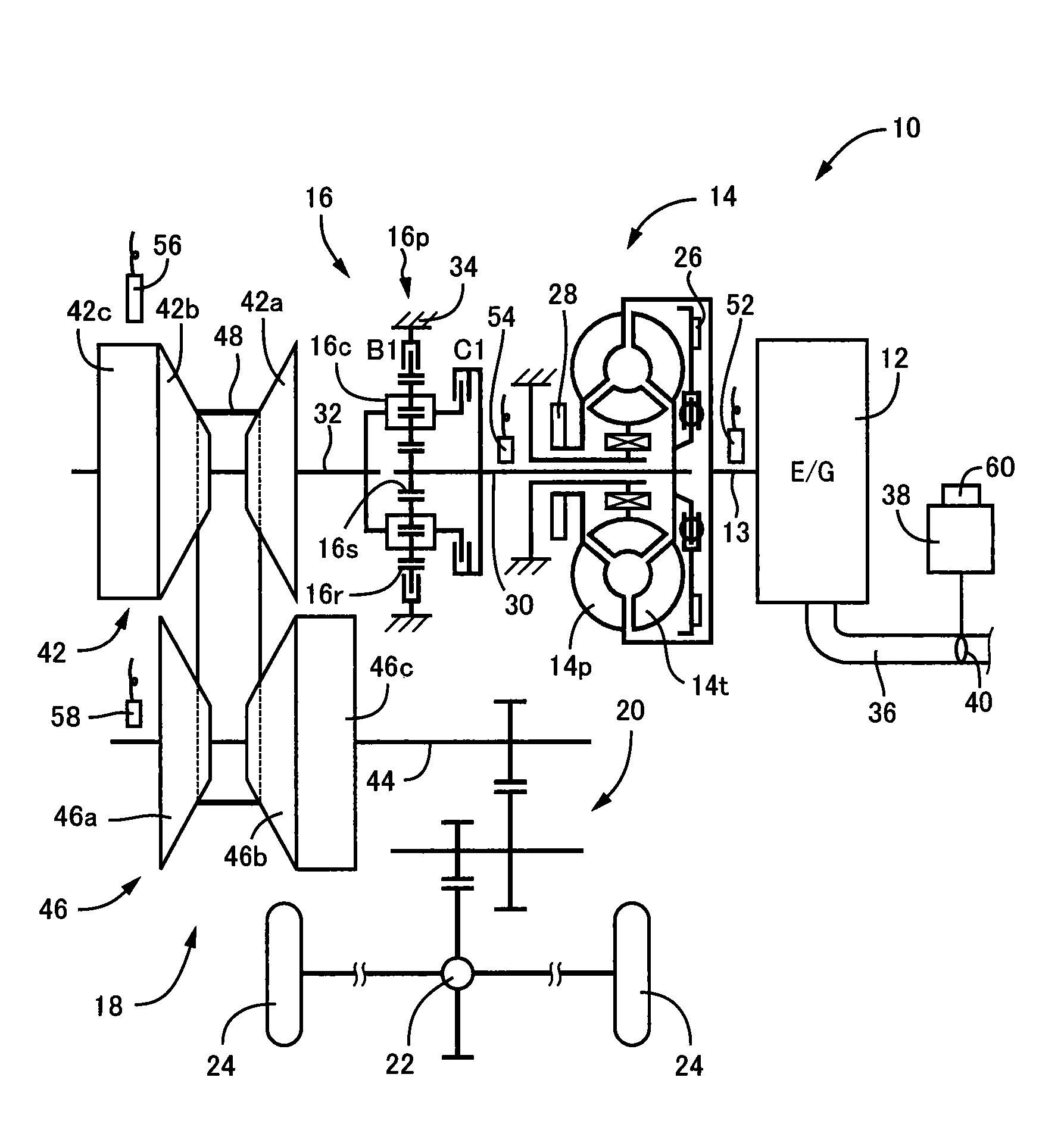
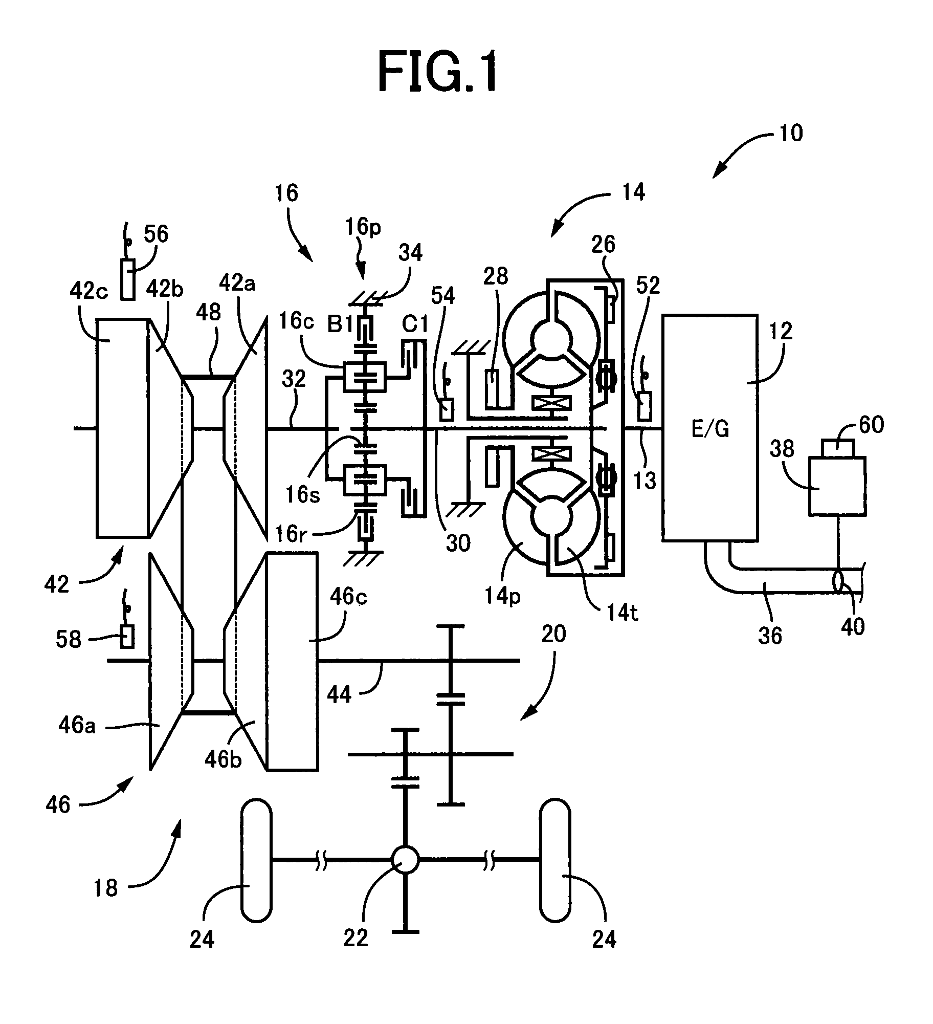
[0030]FIG. 1 is a diagram for explaining a general configuration of a power transmission path from an engine 12 to drive wheels 24 making up a vehicle 10 to which the present invention is applied. In FIG. 1, for example, the power generated by the engine 12 used as a drive force source for running is transmitted sequentially through a torque converter 14 acting as a hydraulic transmission device, a forward / reverse switching device 16, a belt type continuously variable transmission 18 (hereinafter referred to as a continuously variable transmission (CVT)) acting as a continuously variable transmission for a vehicle, a reduction gear device 20, a differential gear device 22, etc., to the left and right drive wheels 24.

[0031]The torque converter 14 includes a pump impeller 14p coupled to a crankshaft 13 of the engine 12 and a turbine impeller 14t coupled to the forward / reverse switching device 16 via a turbine shaft 30 corresponding to an output-side member of the torque converter 14 t...


PUM


Abstract

A control device of a continuously variable transmission for a vehicle has a pair of variable pulleys and a transmission belt, and the control device respectively controls input-side and output-side thrust forces of input-side and output-side variable pulleys to set an actual gear ratio to a target gear ratio, prevents a slip of the transmission belt, and determines a lowest-speed-side gear ratio. When it is determined that a detection value of a rotation speed for calculating the actual gear ratio does not reflect an actual rotation speed, target input-side and output-side thrust forces are set to be target thrust forces for maintaining the lowest-speed-side gear ratio and preventing the slip of the transmission belt, and based on whether the actual gear ratio is already the lowest-speed-side gear ratio, values of the input-side and output-side thrust forces are changed for obtaining the target thrust forces.

Description

TECHNICAL FIELD[0001]The present invention relates to a control device of a continuously variable transmission for a vehicle that is a belt type continuously variable transmission respectively controlling an input-side thrust force and an output-side thrust force to achieve a gear ratio and having a lowest-speed-side gear ratio mechanically determined.BACKGROUND ART[0002]A control device of a continuously variable transmission for a vehicle (hereinafter, continuously variable transmission) is well known that has a pair of variable pulleys with variable effective diameters of an input-side variable pulley (a primary pulley, a primary sheave) and an output-side variable pulley (a secondary pulley, a secondary sheave) and a transmission belt wrapped around between the pair of the variable pulleys and that respectively controls an input-side thrust force (a primary thrust force) in the primary sheave and an output-side thrust force (secondary thrust force) in the secondary sheave to set...

Claims


Application Information

Patent Timeline
Patent Type & Authority Patents(United States)
IPC IPC(8): F16G5/00F16H59/46F16H63/42F16H59/70F16H59/06
CPCF16H61/66272F16H61/66259F16H61/662
Inventor AYABE, ATSUSHITOYODA, SHINYAHATTORI, KUNIO
Owner TOYOTA JIDOSHA KK
Why Eureka
Try Eureka