
Fuel injection control apparatus for internal combustion engine and fuel injection control method for internal combustion engine

a technology of internal combustion engine and control apparatus, which is applied in the direction of electrical control, process and machine control, instruments, etc., can solve the problems of achieve the effect of preventing worsening fuel economy or exhaust characteristi

Active Publication Date: 2014-08-05
TOYOTA JIDOSHA KK
View PDF10 Cites 1 Cited by
  • Summary
  • Abstract
  • Description
  • Claims
  • Application Information

AI Technical Summary

Benefits of technology

[0010]The present invention provides a fuel injection control apparatus for the internal combustion engine and a fuel injection control method for the internal combustion engine that prevent worsening of fuel economy or exhaust characteristic when the OTP boosting is performed by adjusting the OTP boost value to a more appropriate value.
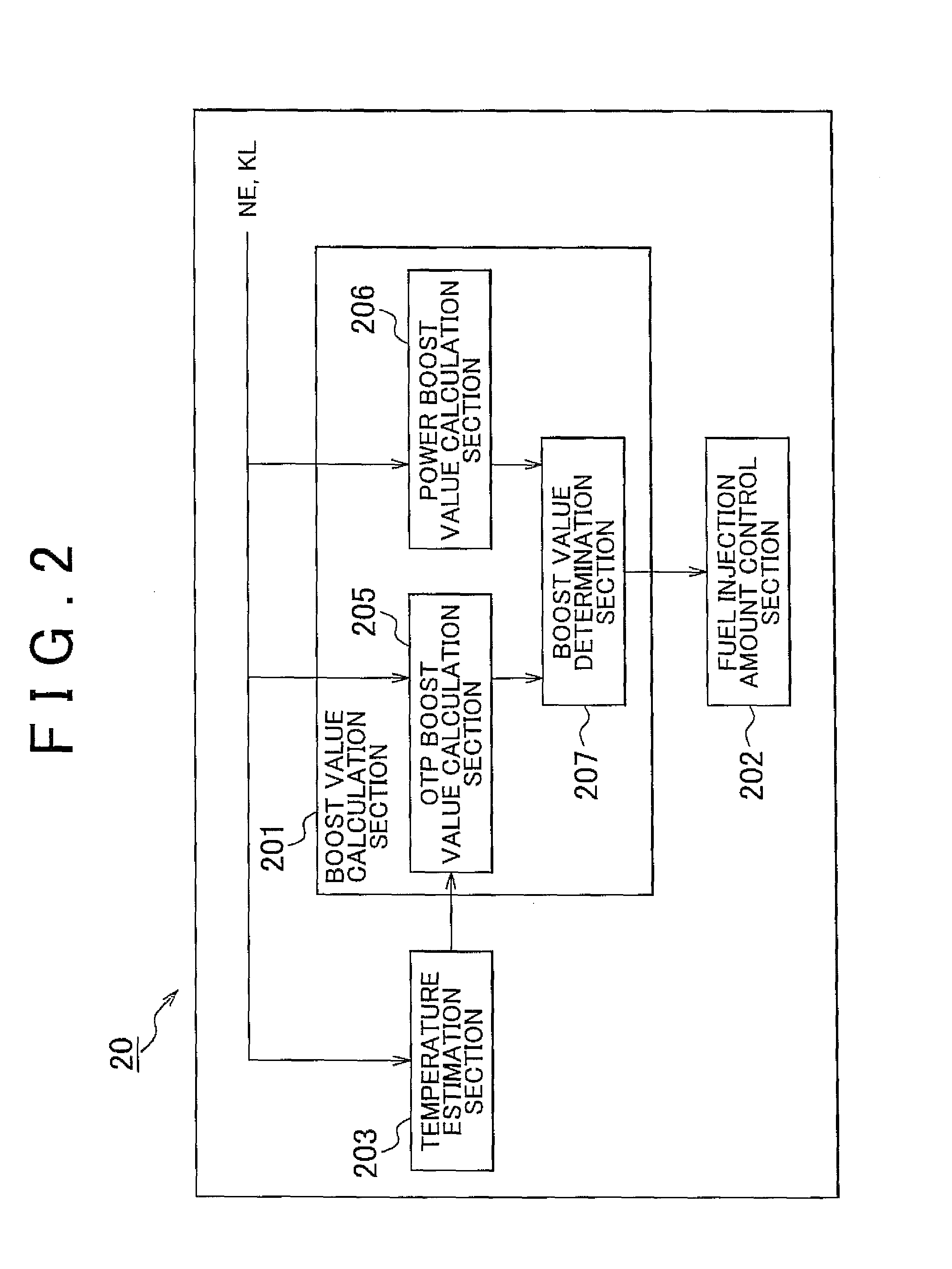
[0013]A fuel injection control method for an internal combustion engine according to a second aspect of the present invention includes: increasing a fuel injection amount by a larger one of an OTP boost value of an OTP boosting and a power boost value of a power boosting when both of an OTP boosting execution condition and a power boosting execution condition are met, in which the OTP boosting execution condition is an execution condition for the OTP boosting that increases the fuel injection amount in order to prevent overheating of an exhaust gas catalytic converter, and the power boosting execution condition is an execution condition for the power boosting that increases the fuel injection amount in order to set air-fuel ratio of mixture to output air-fuel ratio; estimating a convergence temperature of the exhaust gas catalytic converter on the assumption that an operating condition of the internal combustion engine is in a normal operating condition by correcting a reference convergence temperature, which is calculated in accordance with engine speed and engine load, based on a temperature decrement quantity of the exhaust gas catalytic converter which is caused by at least the power boosting; estimating an ordinary temperature that is a current temperature of the exhaust gas catalytic converter on the assumption that an operating condition of the internal combustion engine is in a normal operating condition, in accordance with the convergence temperature; calculating an OTP boost correction value, which is the OTP boost value on the assumption that temperature of the exhaust gas catalytic converter is the ordinary temperature, by correcting an OTP boost reference value, which is the OTP boost value on the assumption that the temperature of the exhaust gas catalytic converter is the convergence temperature, in accordance with the ordinary temperature and the convergence temperature; and selecting either of the OTP boost reference value or the OTP boost correction value as the OTP boost value when the OTP boosting is performed, and in the fuel injection control method, when both of the OTP boosting execution condition and the power boosting execution condition are met, the convergence temperature is estimated on the assumption that the temperature decrement quantity of the exhaust gas catalytic converter which is caused by the power boosting is zero.
[0018]Therefore, in the first and the second aspect of the present invention, when both of the OTP boosting execution condition and the power boosting execution condition are met, the convergence temperature estimation section estimates the convergence temperature on the assumption that the temperature decrement quantity of the exhaust gas catalytic converter which is caused by the power boosting is zero. Accordingly, the convergence temperature is prevented from being calculated as the lower value than the actual convergence temperature. As a result, the OTP boost correction value is prevented from becoming unnecessarily large. Therefore, worsening of fuel economy or exhaust characteristic can be prevented when the OTP boosting is performed.
[0021]According to the first and the second aspect of the present invention; the OTP boost value can be adjusted to a more appropriate value. As a result, worsening of fuel economy or exhaust characteristic can be prevented when the OTP boosting is performed.

Problems solved by technology

When the OTP boost value in OTP boosting is excessively large with respect to the temperature of the exhaust gas catalytic converter, it may result in worsening of fuel economy or exhaust characteristic.

Method used


Image

  • Fuel injection control apparatus for internal combustion engine and fuel injection control method for internal combustion engine
  • Fuel injection control apparatus for internal combustion engine and fuel injection control method for internal combustion engine
  • Fuel injection control apparatus for internal combustion engine and fuel injection control method for internal combustion engine

Examples


embodiment 1

[0034][Schematic Structure of Intake and Exhaust Systems for Internal Combustion Engine]

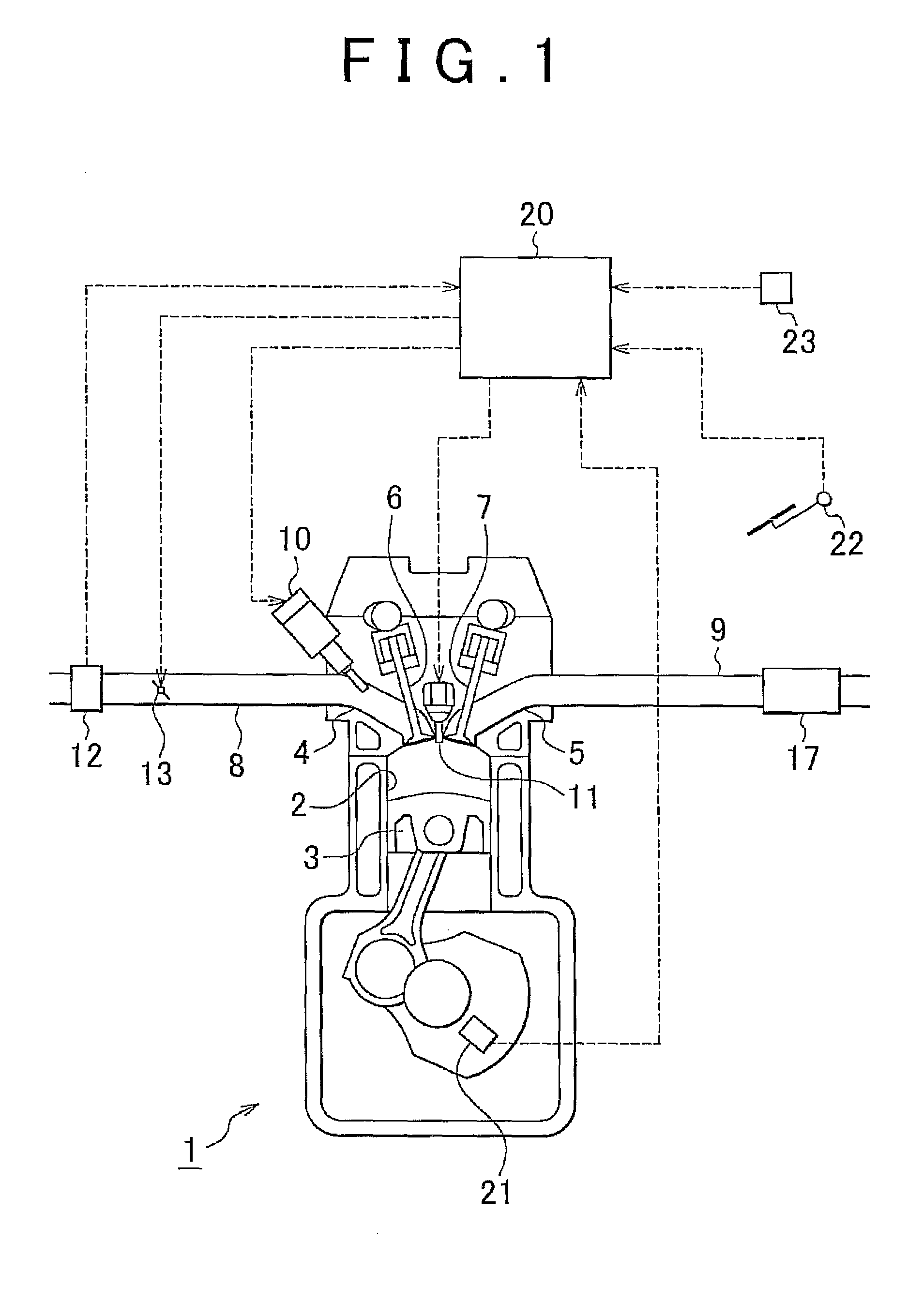
[0035]FIG. 1 is a schematic view that shows the structure of an intake and an exhaust system for the internal combustion engine according to this embodiment. The internal combustion engine 1 is a gasoline engine for driving a vehicle which has four cylinders 2. However, the internal combustion engine according to the present invention is not limited to the gasoline engine, but may be a diesel engine, for example.

[0036]A piston 3 is slidably disposed within a cylinder 2. An intake port 4 and an exhaust port 5 are connected to a combustion chamber in an upper section in the cylinder 2. Openings of the intake port 4 and the exhaust port 5 to the combustion chamber are opened or closed by an intake valve 6 and an exhaust valve 7, respectively.

[0037]A fuel injection valve 10 and a spark plug 11 are installed in the internal combustion engine 1. The fuel injection valve 10 sprays fuel into the intake p...

embodiment 2

[0083][Fuel Injection Control]

[0084]Schematic structure of the intake and the exhaust systems for the internal combustion engine according to this embodiment is the same as Embodiment 1. Hereinafter, the fuel injection control according to this embodiment will be described mainly about the points different from Embodiment 1.

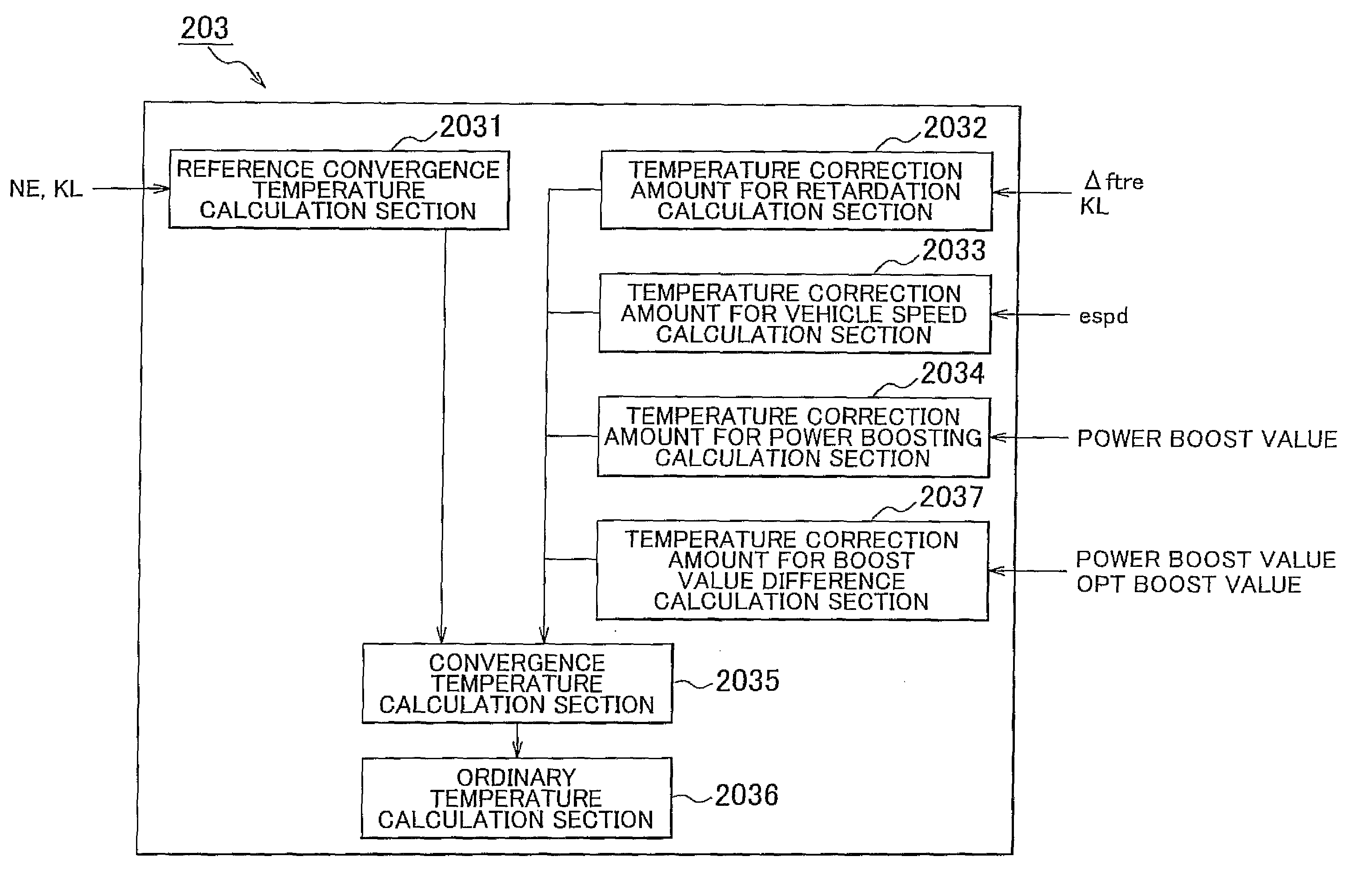
[0085]FIG. 8 is a block diagram that shows an outline of functional components of the temperature estimation section 203 according to this embodiment. The temperature estimation section 203 according to this embodiment includes a reference convergence temperature calculation section 2031, a temperature correction amount for retardation calculation section 2032, a temperature correction amount for vehicle speed calculation section 2033, a temperature correction amount for power boosting calculation section 2034, a convergence temperature calculation section 2035, an ordinary temperature calculation section 2036, and in addition a temperature correction amount for ...


PUM


Abstract

A fuel injection control for an internal combustion engine includes: estimating a convergence temperature of the exhaust gas catalytic converter; calculating an OTP boost value using the estimated convergence temperature; and estimating the convergence temperature on the assumption that the temperature decrement quantity of the exhaust gas catalytic converter which is caused by the power boosting is zero when both of the OTP boosting execution condition and the power boosting execution condition are met.

Description

CROSS REFERENCE TO RELATED APPLICATIONS[0001]This application claims priority to Japanese Patent Application No. 2011-025103 filed on Feb. 8, 2011, which is incorporated herein by reference in its entirety including the specification, drawings and abstract.BACKGROUND OF THE INVENTION[0002]1. Field of the Invention[0003]The present invention relates to a fuel injection control apparatus for an internal combustion engine and a fuel injection control method for the internal combustion engine.[0004]2. Description of Related Art[0005]For fuel injection amount control for the internal combustion engine, a boost correction such as so-called over-temperature protection (OTP) boosting or power boosting is known to increase and correct the fuel injection amount more than a normal operating condition of the engine. The OTP boosting is a boost correction of the fuel injection amount that is performed to prevent overheating of an exhaust gas catalytic converter. When the fuel injection amount is...

Claims


Application Information

Patent Timeline
Patent Type & Authority Patents(United States)
IPC IPC(8): F02D41/10
CPCF02D41/0235F02D41/10F02D2041/0265F02D2200/0618F02D2200/0804F02D2200/501
Inventor KACHI, MASAHIROTAKAMA, YASUYUKI
Owner TOYOTA JIDOSHA KK
Learn More