
Hand-held aerosol fire suppression apparatus

a fire suppression apparatus and handheld technology, applied in fire rescue and other directions, can solve the problems reducing the safety of the apparatus, and reducing the time required for removing the jet nozzle. the effect of reducing the time required for removing the jet nozzl

Inactive Publication Date: 2014-08-12
SHAANXI J&R FIRE FIGHTING CO LTD
View PDF13 Cites 4 Cited by
  • Summary
  • Abstract
  • Description
  • Claims
  • Application Information

AI Technical Summary

Benefits of technology

The present invention is a new aerosol fire suppression apparatus that is safer, has a faster flame, and releases aerosol quickly. Compared to previous versions, this apparatus has advantages such as reducing the time required to remove the jet nozzle, improving safety features, and integrating the safety mechanism and switch mechanism. It is easy to operate and has a higher safety factor. The structure and assembly design of the apparatus allows for smoother aerosol release and better cooling.

Problems solved by technology

In our working and living environments in modern times, fire hazard exists everywhere in limited spaces, such as machines, electrical devices, automobiles, electric cabinets, all kinds of household electric appliances, computers, TV sets, kitchens, etc., and spontaneous ignition of wires or engines often occur due to extremely high temperature.
Usually, using a hand-held fire suppression apparatus to suppress such small-scale fire timely can get twice the result with half the effort.
The fire suppression products have the following major drawbacks: (1) The aerosol spurts out directly after the medical is ignited, the temperature at the jet orifice is as high as 1200° C., the flame length is up to 100 mm, and may cause scalding; (2) The handle doesn't have enough strength, and may deform when force is applied on it; in addition, the battery is difficult to install, and there is no way to judge whether the battery has to be replaced or not after the battery is used for a long time.
There is more or less potential safety risk in all existing hand-held aerosol fire suppression apparatuses in the prior art.

Method used


Image

  • Hand-held aerosol fire suppression apparatus
  • Hand-held aerosol fire suppression apparatus
  • Hand-held aerosol fire suppression apparatus

Examples


Embodiment Construction

[0020]The embodiments of the present invention will be further detailed with reference to the drawings.

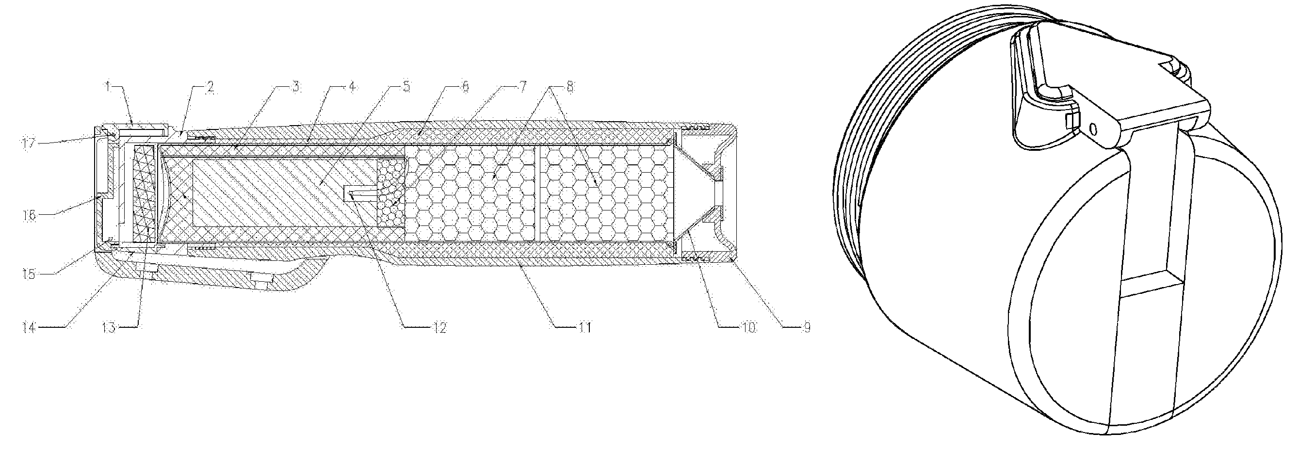
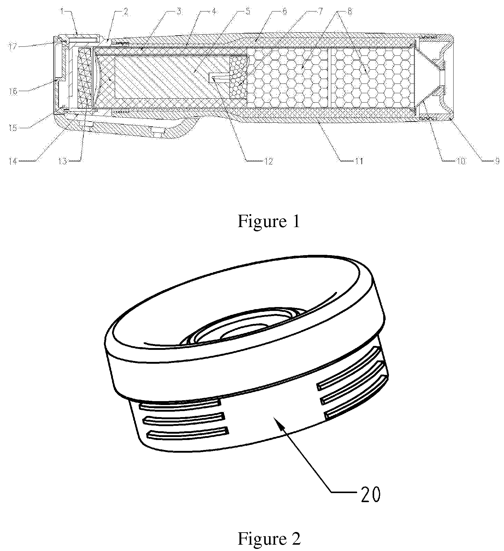
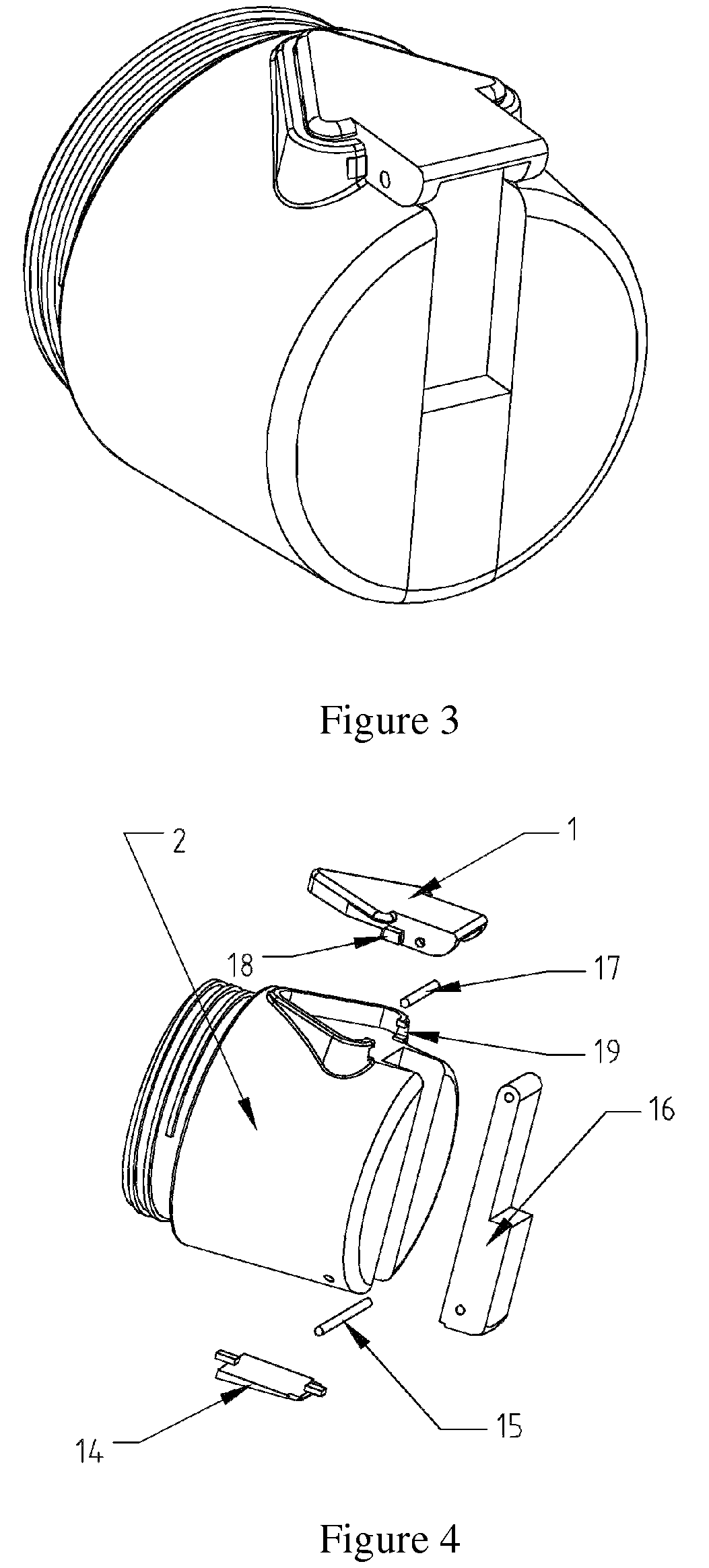
[0021]FIG. 1 is a schematic structural diagram of an example of the hand-held aerosol fire suppression apparatus in the present invention. As shown in FIG. 1, the hand-held aerosol fire suppression apparatus has a cylindrical enclosure 11 and an inner cylinder 4; in addition, the apparatus comprises rear cap 2, inner cylinder 4, aerosol generating agent 5 in the inner cylinder, ignition head 5 arranged at the center of the aerosol generating agent 5, tabular coolant 7, cellular coolant 8, tapered jet orifice 10, and jet nozzle 9; wherein the tabular coolant 7 is arranged between the aerosol generating agent 5 and the cellular coolant 8. The inner cylinder 4 is installed in the enclosure 11, and the rear cap 2 and jet nozzle 9 are screwed to the enclosure 11 respectively.

[0022]Moreover, a piezoelectric crystal assembly 13 is arranged between the rear cap 2 and the enclosure 11. The ...


PUM


Abstract

The present invention relates to a novel hand-held aerosol fire suppression apparatus, comprising thermal insulating layer (3), inner cylinder (4), aerosol generating agent (5), heat insulating material (6), jet nozzle (9), tapered jet orifice (10), enclosure (11), ignition head (12) and piezoelectric crystal assembly (13), wherein the thermal insulating layer (3) is arranged between the inner cylinder (4) and the aerosol generating agent (5), and the jet nozzle (9) is screwed to the enclosure (11) by means of a thread structure that comprises 3˜6 thread segments. Compared to that in the prior art, with the segment thread design for screwing the jet nozzle to the enclosure, the time required for removing the jet nozzle can be reduced significantly, and therefore the apparatus in the present invention has much better safety feature against accidents.

Description

CROSS REFERENCE TO RELATED APPLICATIONS[0001]This is a U.S. National Phase patent application of PCT / CN2010 / 074961, filed Jul. 3, 2010, which claims priority to Chinese Patent Application No. 201020102303.1, filed Jan. 26, 2010, each of which is hereby incorporated by reference in the present disclosure in its entirety.FIELD OF THE INVENTION[0002]The present invention belongs to the technical field of gas fire suppression, and relates to a novel hand-held aerosol fire suppression apparatus.BACKGROUND OF THE INVENTION[0003]In our working and living environments in modern times, fire hazard exists everywhere in limited spaces, such as machines, electrical devices, automobiles, electric cabinets, all kinds of household electric appliances, computers, TV sets, kitchens, etc., and spontaneous ignition of wires or engines often occur due to extremely high temperature. Usually, using a hand-held fire suppression apparatus to suppress such small-scale fire timely can get twice the result wi...

Claims


Application Information

Patent Timeline
Patent Type & Authority Patents(United States)
IPC IPC(8): A62C13/00A62C5/00
CPCA62C13/003A62C5/006A62C13/22A62C5/00A62C31/02A62C31/28
Inventor GUO, HONGBAOZHANG, KUNMA, CHUNJIEZHAI, TENGFEIDENG, ZHENPING
Owner SHAANXI J&R FIRE FIGHTING CO LTD
Learn More