Sample injector for liquid chromatography, particularly for high performance liquid chromatography

Active Publication Date: 2014-08-19
DIONEX SOFTRON
View PDF21 Cites 35 Cited by
  • Summary
  • Abstract
  • Description
  • Claims
  • Application Information

AI Technical Summary

Benefits of technology

[0007]The invention includes a sample injector for liquid chromatography, particularly for high performance liqu

Problems solved by technology

Furthermore, WO 2006/083776 discloses a sample injector for preventing pressure surges that occur during the actuation of the high-pressure valve and could negatively affect the efficiency and the service life of the chromatography column.
According to non-previously-published German Paten

Method used


Image

  • Sample injector for liquid chromatography, particularly for high performance liquid chromatography
  • Sample injector for liquid chromatography, particularly for high performance liquid chromatography
  • Sample injector for liquid chromatography, particularly for high performance liquid chromatography

Examples


Example

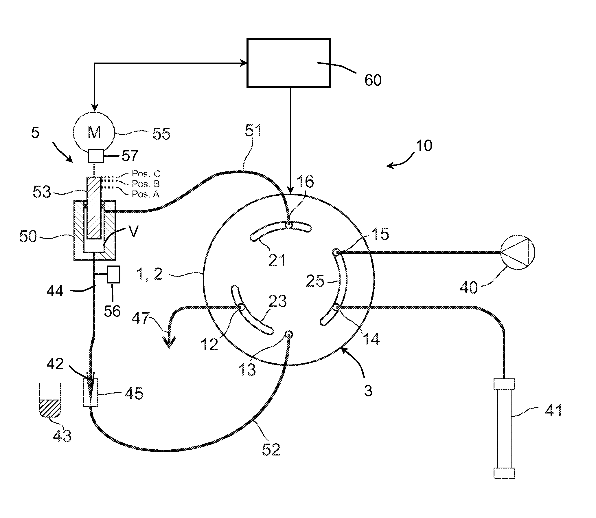
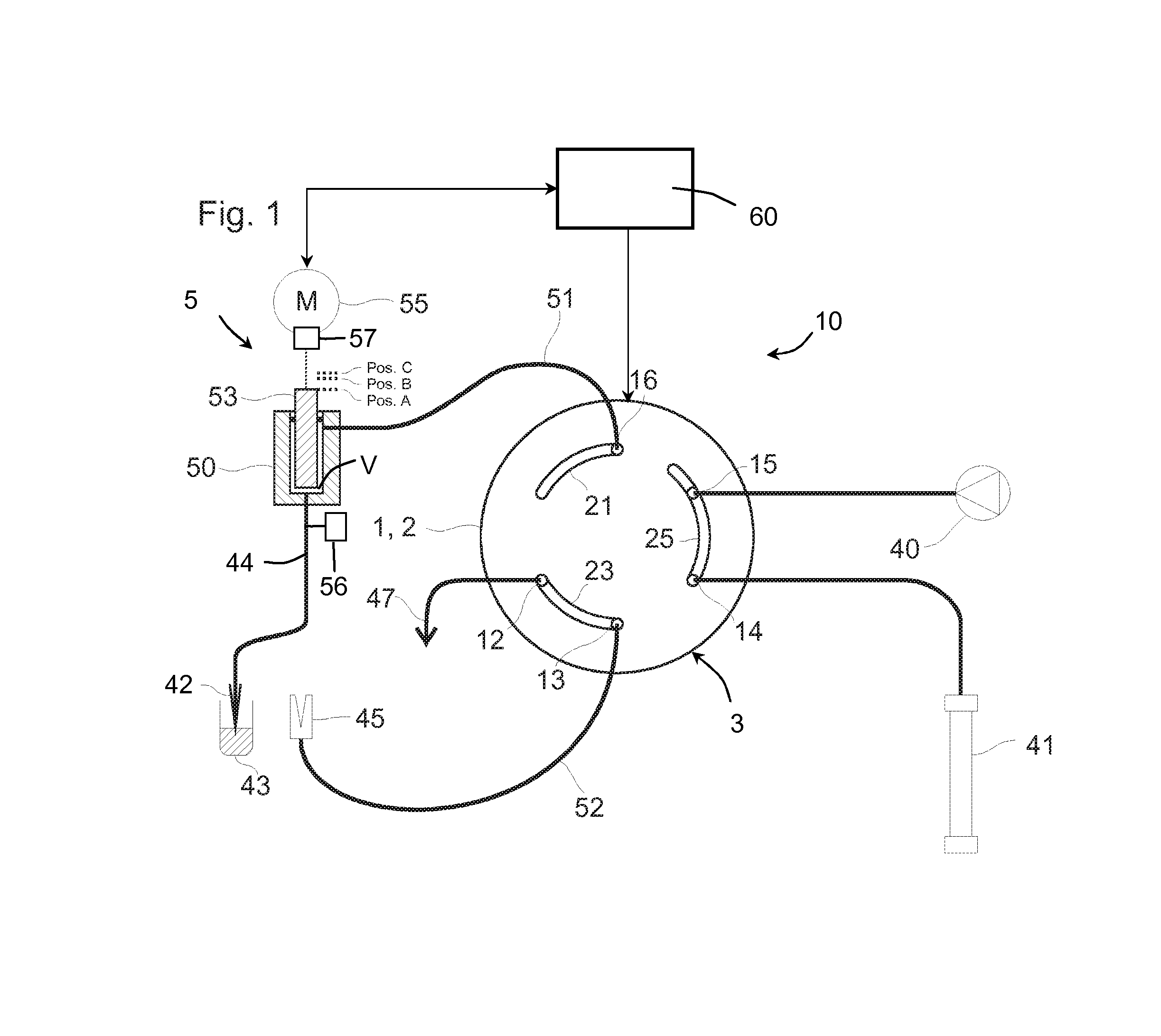
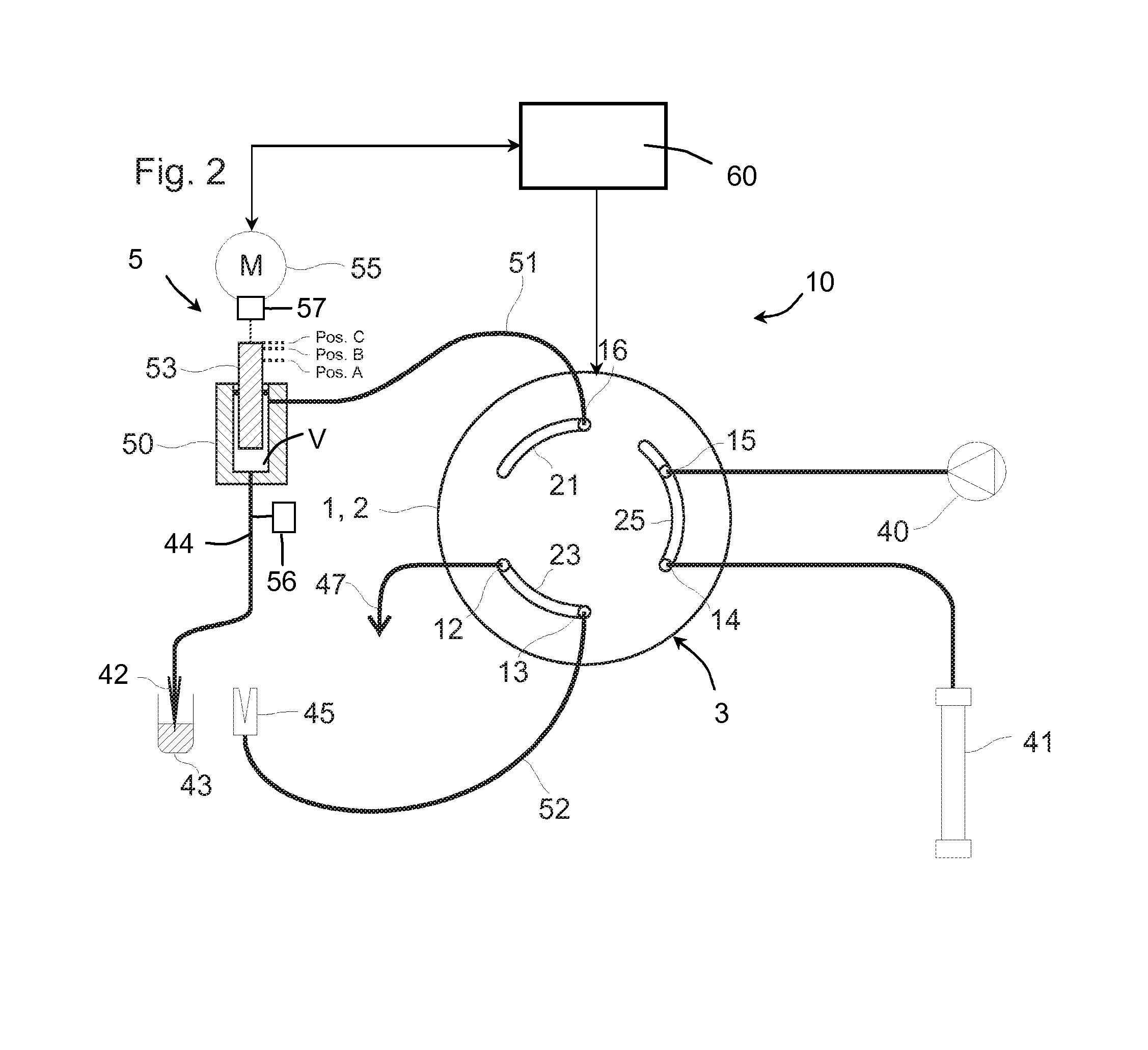
[0033]FIG. 1 shows a schematic representation of an HPLC system with a sample injector 10 that operates in accordance with the Split Loop Principle and features a sample conveying device 5, an injection valve 3 and a high-pressure pump 40. The sample injector 10 furthermore features a sample loop that includes a first connecting piece 51 and a second connecting piece 52, 44. These may be comprised of a pressure-resistant line with a small diameter, for example in the form of a capillary tube of glass or stainless steel. The connecting piece 51 is connected to a first sample loop port 16 of the injection valve 3 and to the sample conveying device or its pump volume V, respectively. The second connecting piece is comprised of an intake segment 44 and a feed segment 52 and is realized in a separable fashion. For this purpose, the feed segment 52 leads into an injection port 45 that is connected to a second sample loop port 13 of the injection valve 3 via the feed segment 52. The intake...


PUM


Abstract

A sample injector for liquid chromatography includes an injection valve having a waste port, two sample loop ports, and two high-pressure ports. One high-pressure port can be connected to a pump and the other high-pressure port can be connected to a chromatography column. A sample loop is connected to one of the sample loop ports on one end and to a pump volume of a sample conveying device on the other end. A section of the sample loop can be separated to facilitate receiving a sample fluid in the sample loop. A control unit controls the injection valve and the sample conveying device. The sample injector allows a sample to be loaded into the sample loop and then pressurized to an operating pressure prior to injecting the sample into the chromatography column. The sample loop may also be isolated from the operating pressure for facilitating depressurization of the loop.

Description

TECHNICAL FIELD OF THE INVENTION[0001]The invention pertains to a sample injector for liquid chromatography, particularly for high performance liquid chromatography (HPLC). The sample injector provides for pressure compensation during a sample injection sequence, or during a post sample injection sequence, or during both sequences.BACKGROUND OF THE INVENTION[0002]In HPLC, a sample to be examined needs to be injected into a high-pressure fluid flow, wherein this flow can be interrupted only as briefly as possible. For this purpose, high-pressure injection valves are used that allow a nearly uninterrupted change-over of the fluid flow. Such a design is described, for example, in U.S. Pat. No. 3,530,721. This patent was derived from an original application that was published in 1965.[0003]U.S. Pat. No. 4,939,943 discloses a sample injector with a “high pressure syringe unit.” The basic Split Loop Principle of the sample injector disclosed in this application has proven effective in HPL...

Claims


Application Information

Patent Timeline
IPC IPC(8): G01N13/00G01N30/24
CPCG01N30/24G01N30/32G01N2030/201G01N35/1097G01N2030/207G01N30/20G01N2030/027
Inventor HOCHGRAEBER, HERMANN
Owner DIONEX SOFTRON
Why Eureka
Try Eureka