
Ink jet print head with piezoelectric actuator

a piezoelectric actuator and print head technology, applied in printing and other directions, can solve the problems of limiting the usable amount of deflection and tensile stress of pzt film

Active Publication Date: 2014-08-19
OCE TECH
View PDF9 Cites 2 Cited by
  • Summary
  • Abstract
  • Description
  • Claims
  • Application Information

AI Technical Summary

Benefits of technology

This patent describes an ink jet print head with a piezoelectric actuator that has improved pressure generation ability. The use of a titanium-tungsten alloy as the upper electrode helps to reduce or cancel out a net tensile stress of the substrate and actuator, which reduces or eliminates deflection. The use of a thinner titanium-tungsten film helps to increase efficiency, reduce energy consumption, and maintain high printing quality for a longer period of time. Additionally, a moisture barrier layer is applied to prevent moisture from penetrating the piezo-actuator.

Problems solved by technology

This results in tensile stress in the PZT film.
An inherent deflection of an actuator membrane comprising such a PZT film limits the usable amount of deflection when the piezoelectric actuator is energized.

Method used


Image

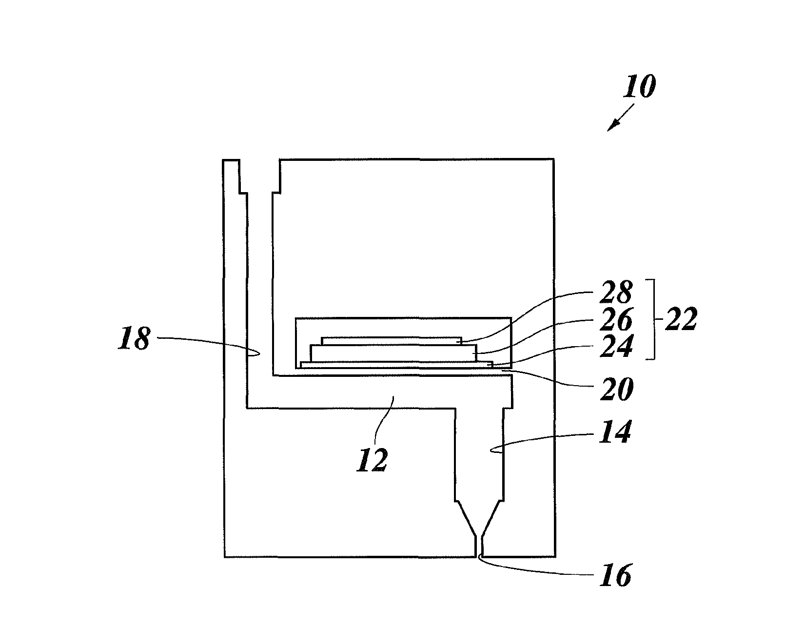
  • Ink jet print head with piezoelectric actuator
  • Ink jet print head with piezoelectric actuator
  • Ink jet print head with piezoelectric actuator

Examples


first embodiment

[0048]Table 1 shows three examples of layer thicknesses of the first embodiment which satisfy the above formula.

[0049]

TABLE 1Layer ThicknessLayer ThicknessLayer Thickness(nm)(nm)(nm)LayerExample 1Example 2Example 3TiW230150110PZT300020002000Pt300200100Ti303030SiO2500500500Si500050005000SiO2500500500

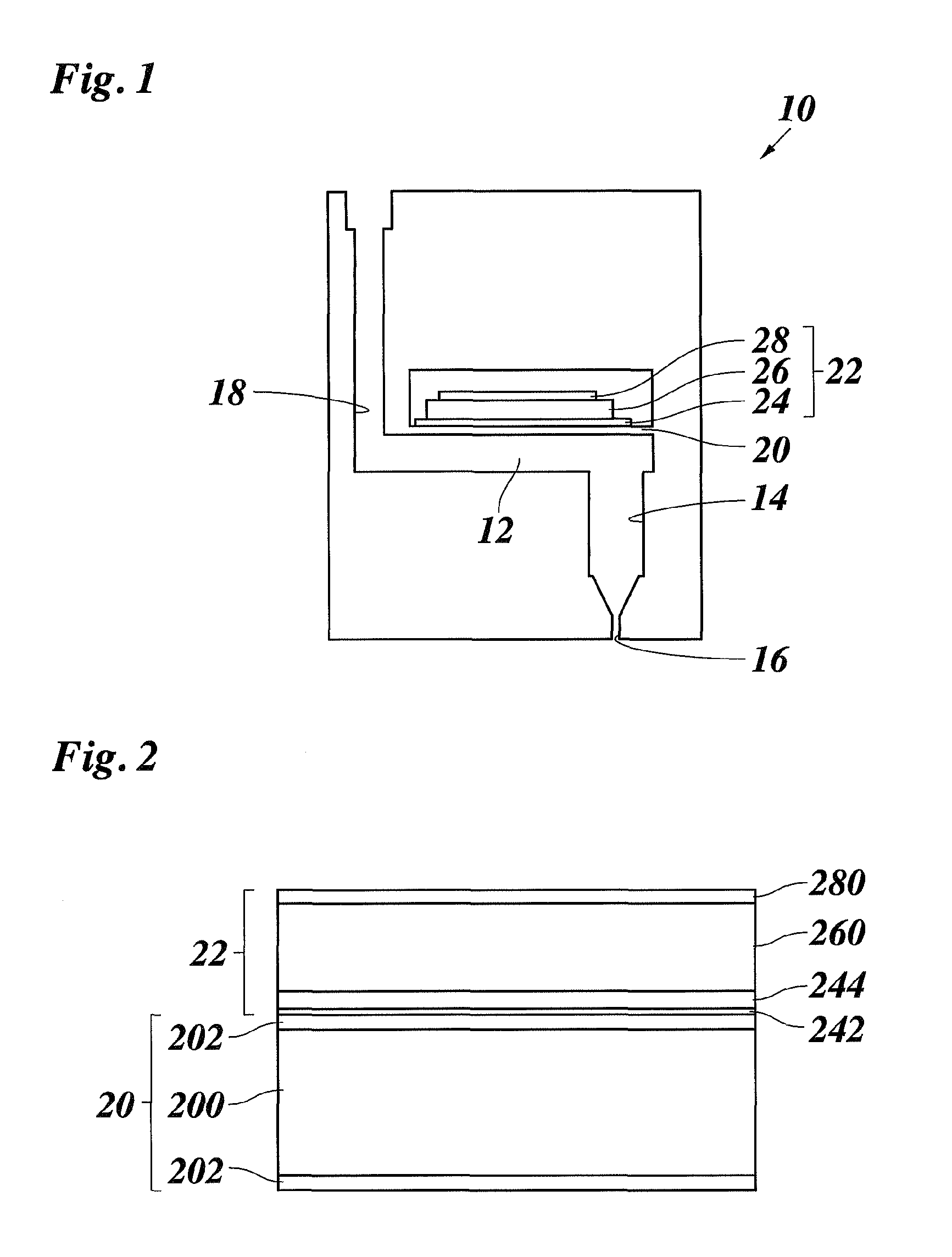
[0050]In the examples, the silicon layer 200 of the silicon substrate 20 has a thickness of 5000 nanometer, and the surface oxide layers 202 have a thickness of 500 nanometer each.

[0051]With a Pt layer 244 of 300 nanometer and a PZT layer 260 of 3000 nanometer, a TiW layer 280 having a thickness of 230 nanometer is expected to have a compressive stress that leads to a flatness of the multilayer package and, thus, the substrate 20.

[0052]With a PZT layer of 2000 nanometer, a TiW layer of 150 nanometer is sufficient for a lower electrode having a Pt layer of 200 nanometer, and a TiW layer of 110 nanometer is sufficient for a lower electrode Pt layer of 100 nanometer. Thus, the upper electrod...

second embodiment

[0053]FIG. 3 shows an actuator membrane in the form of a multilayer package of a second embodiment having a silicon nitride (Si3N4) substrate 30. The substrate 30 and the piezoelectric actuator 22 form a multilayer package consisting of the Si3N4 layer of the substrate 30, an adhesion layer 242 of Titanium, a platinum layer 244, a PZT layer 280 and a TiW layer 280.

[0054]The layers may be prepared similar to the embodiment of FIG. 2. The piezoelectric actuator comprises the Ti adhesion layer 242 and the Pt layer 244 of the lower electrode 24, the piezoelectric layer 26 consisting of the PZT layer 260 and the upper electrode consisting of the Titanium-Tungsten film 280.

[0055]Table 2 shows layer thicknesses of two examples of the second embodiment.

[0056]

TABLE 2Layer thickness (nm)Layer thickness (nm)LayerExample 1Example 2TiW85100PZT10002000Pt100100Ti3030Si3N410001000

[0057]For example, the substrate 30 has a thickness of 1000 nanometer. The adhesion layer 242 has a thickness of 30 nano...


PUM


Abstract

An ink jet print head, having a pressure generation chamber arranged for being in communication with a print head nozzle and an actuator membrane for delimiting the pressure generation chamber. The actuator membrane has a substrate and a piezoelectric actuator provided on the substrate, said piezoelectric actuator having a lower electrode, an upper electrode and at least one piezoelectric layer arranged between the lower electrode and the upper electrode; the substrate and the upper electrode are arranged on opposite sides of the piezoelectric layer, and the upper electrode has a Titanium-Tungsten film.

Description

CROSS REFERENCE TO RELATED APPLICATIONS[0001]This application is the Continuation of PCT / EP2011 / 070536 filed on Nov. 21, 2011, which claims priority under 35 U.S.C. 119(a) to European Patent Application No. 10193127.7 filed on Nov. 30, 2010, all of which are hereby expressly incorporated by reference into the present application.BACKGROUND OF THE INVENTION[0002]1. Field of the Invention[0003]The invention relates to an ink jet print head, in particular an ink jet print head comprising a piezoelectric actuator. In particular, the invention relates to an ink jet print head, in which a piezoelectric actuator is arranged to be used in a deflection mode for deflecting an actuator membrane in order to pressurize ink in a pressure generation chamber.[0004]2. Description of Background Art[0005]U.S. Pat. No. 7,101,026 B2 describes different types of ink jet recording heads. A piezoelectric element is placed on one side of a flow passage formation substrate via a diaphragm and has a lower ele...

Claims


Application Information

Patent Timeline
Patent Type & Authority Patents(United States)
IPC IPC(8): B41J2/045B41J2/14
CPCB41J2/14201B41J2/14233B41J2002/14241
Inventor SHKLYAREVSKIY, IGOR O.WESTLAND, ALEX N.
Owner OCE TECH
Learn More