Inverter generator

a technology of inverter generator and generator body, which is applied in the direction of electric generator control, engine starter, machine/engine, etc., can solve the problems of increasing the size of the generator, increasing the weight and size of the generator as a whole, and achieving the effect of increasing cost and being light and compa

Active Publication Date: 2014-08-19
HONDA MOTOR CO LTD
View PDF41 Cites 3 Cited by
  • Summary
  • Abstract
  • Description
  • Claims
  • Application Information

AI Technical Summary

Benefits of technology

[0008]An object of embodiments of this invention is therefore to overcome the foregoing problem by providing an inverter generator equipped with a generator unit driven by an engine, which can start the engine using the generator unit and can be made light and compact without increasing cost.

Problems solved by technology

However, such a configuration is disadvantageous because the installation of the starter motor causes increase in size of the generator.
Accordingly, when, for instance, the line-to-line voltage of the winding is set relatively high, the voltage that enables the rotating operation is also increased, so that a boost ratio of the converter also rises and it leads to increase in size of the converter.
As a result, the generator as a whole is increased in weight and size, disadvantageously.
In addition, as to parts (e.g., a capacitor, etc.) to which a relatively-high voltage is applied from the generator unit at power generation, a voltage-endurance property is needed to be enhanced, resulting in increase in size and cost.
It is also inconvenient.

Method used


Image

  • Inverter generator
  • Inverter generator
  • Inverter generator

Examples


first embodiment

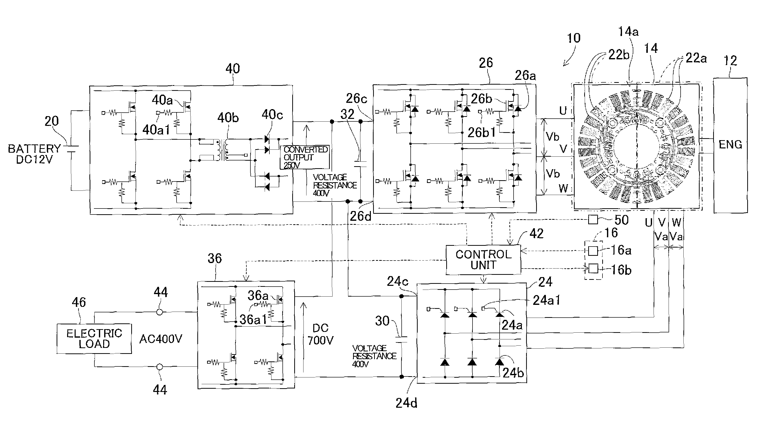
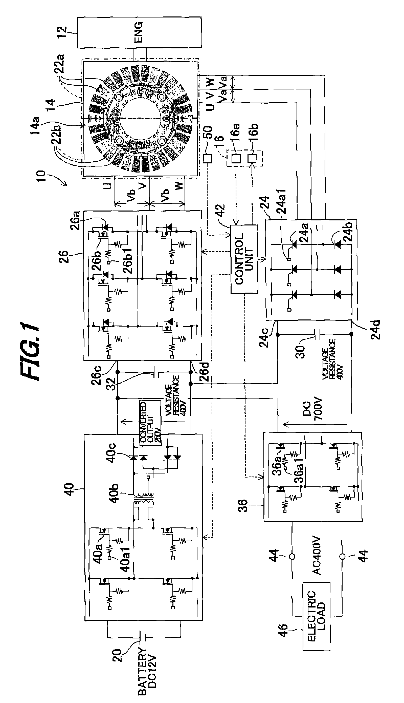
[0019]FIG. 1 is an overall block diagram showing an inverter generator according to the invention. FIG. 6 is an overall block diagram similar to FIG. 1, but showing an inverter generator according to a conventional technique.

[0020]As shown in FIG. 6, an inverter generator 200 is equipped with a generator unit (starter generator) 204 driven by an engine 202 and has a rated output voltage of AC 400V (maximum voltage: 750V). The generator unit 204 is wound by an output winding 206 and a line-to-line voltage V1 to be generated at the output winding 206 (i.e., an output voltage of the generator unit 204) when power is generated is defined by the rated output voltage of the inverter generator 200, specifically, 500V. The line-to-line voltage defined in accordance with the rated output voltage of the generator is hereinafter called the “defined line-to-line voltage.”

[0021]The engine 202 is started upon rotating operation of the generator unit 204. To be more specific, a control unit 208 ha...

second embodiment

[0066]An inverter generator according to this invention will now be explained.

[0067]The explanation of the second embodiment will focus on the points of difference from the first embodiment. In the second embodiment, a line-to-line voltage Va of a first winding 122a is set to the defined line-to-line voltage while a line-to-line voltage Vb of a second winding 122b is set lower than that of the first winding 122a, and the output of the battery 20 is supplied to the second winding 122b to start the engine 12.

[0068]FIG. 5 is an overall block diagram similar to FIG. 1, but showing the inverter generator 110 according to the second embodiment of the invention. Note that constituent elements corresponding to those of the first embodiment are assigned by the same reference symbols as those in the first embodiment and will not be explained.

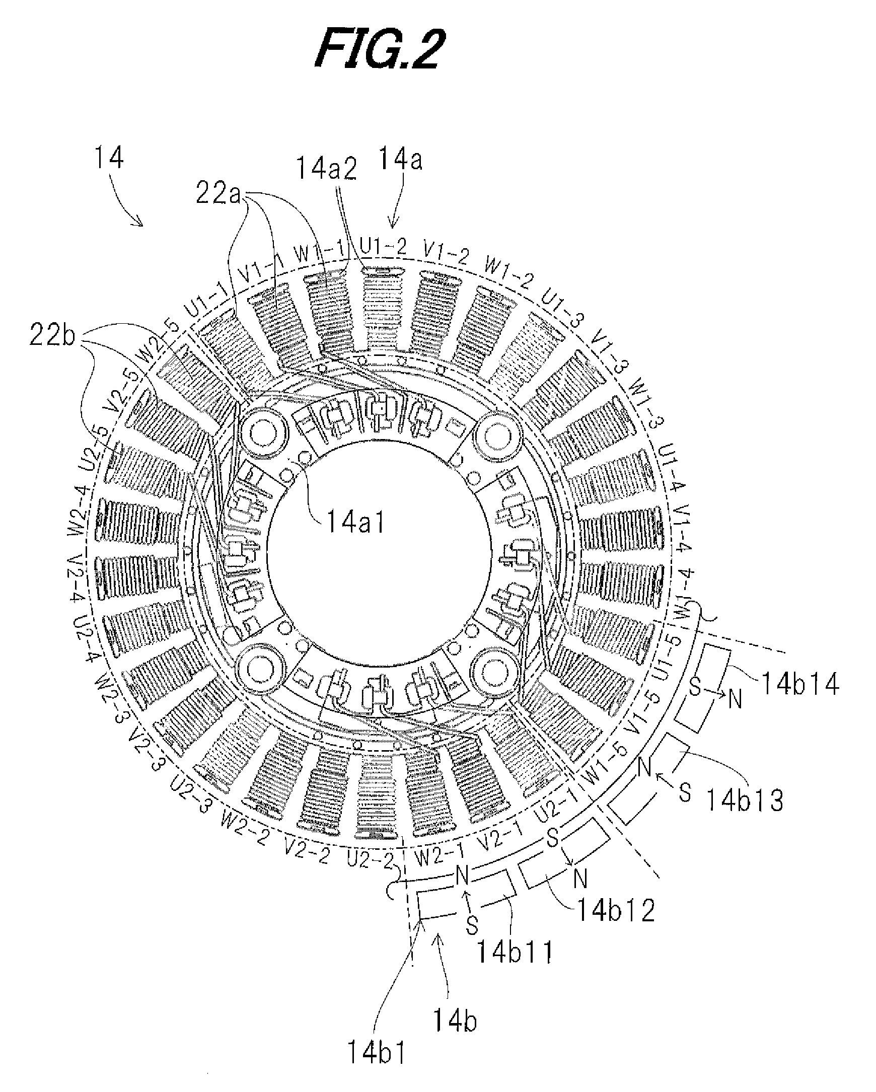
[0069]As shown in FIG. 5, windings of a generator unit 114 include the first winding 122a and second winding 122b, similarly to the first embodiment. The...


PUM


Abstract

In an inverter generator having a winding wound around a generator unit driven by an engine, a converter connected to the winding and adapted to convert an alternating current outputted from the winding to a direct current, an inverter connected to the converter and adapted to invert the direct current outputted from the converter to an alternating current and output it, and a controller adapted to control operations of the converter and the inverter, a battery is connected to the engine, and the winding includes a first winding and a second winding, such that the controller supplies an output of the battery to one of the first winding and the second winding to rotate the generator unit to start the engine.

Description

BACKGROUND OF THE INVENTION[0001]1. Technical Field[0002]Embodiments of the invention relate to an inverter generator, particularly to an inverter generator equipped with a generator unit driven by an engine.[0003]2. Background Art[0004]Conventionally, a technique for an inverter generator equipped with a generator unit driven by an engine is widely known in which a starter motor (cell motor) is used to crank the engine to start it. However, such a configuration is disadvantageous because the installation of the starter motor causes increase in size of the generator.[0005]To deal with it, in Japanese Laid-Open Patent Application No. 2004-340055, the starter motor is removed and a battery output is supplied to the generator unit to rotate it so as to start the engine, i.e., the generator unit is utilized as the starter motor to start the engine, thereby making the generator compact.SUMMARY[0006]In the case of being configured as in the reference, it is necessary to boost a battery vo...

Claims


Application Information

Patent Timeline
Patent Type & Authority Patents(United States)
IPC IPC(8): F02B63/04F02N11/04H02P9/04B60L11/14H02K23/52F03G7/08F02N11/08B60L50/15B60L50/16
CPCF02N11/04B60L11/14Y02T10/7077F02N2011/0896F02N2011/0892Y02T10/70B60L50/16Y02T10/7072
Inventor YAMAMURA, YOICHITAMURA, MINORU
Owner HONDA MOTOR CO LTD
Why Eureka
Try Eureka