Time-of-flight based imaging system using a display as illumination source

a technology of illumination source and imaging system, which is applied in the field of time-of-flight based imaging system, can solve the problems of power consumption, safety, and cost limitations, and still exist speed requirements on the sensor, and achieve the effects of low power consumption, easy implementation, and flexible imaging system

Inactive Publication Date: 2014-08-19
ECOLE POLYTECHNIQUE FEDERALE DE LAUSANNE (EPFL)
View PDF3 Cites 25 Cited by
  • Summary
  • Abstract
  • Description
  • Claims
  • Application Information

AI Technical Summary

Benefits of technology

[0018]The imaging system of the present invention does not require a separate illumination unit and can be optimized to operate at low power. The imaging system is also versatile since it can easily be implemented in various configurations including, for example, mobile devices, computer displays and game consoles, possibly in a low cost configuration.

Problems solved by technology

However, power, safety, and cost limitations still exist.
The main disadvantage of such systems is the speed requirement on the sensor, power dissipation, and a somewhat limited precision.
However, interferometers are usually bulky and very expensive.
Since the charge carrier transport mechanism of most CCDs is based on a thermal diffusion process rather than on a drift effect, the maximum achievable demodulation frequency is severely limited.
The use of a separate illumination unit using a laser or LEDs increases the cost and complexity of manufacture of the camera unit because an additional component, the LED module, must be provided together with appropriate electrical connectors, power supplies and electronics.
Separate illumination also increases the volume of the camera and requires additional power.
These drawbacks are undesirable in most applications and become critical in particular in mobile consumer applications that demand low power, small volume and low cost.
Indeed, these drawbacks of currently used illumination units limit the use of 3D TOF imaging on mobile devices.

Method used


Image

  • Time-of-flight based imaging system using a display as illumination source
  • Time-of-flight based imaging system using a display as illumination source
  • Time-of-flight based imaging system using a display as illumination source

Examples


Embodiment Construction

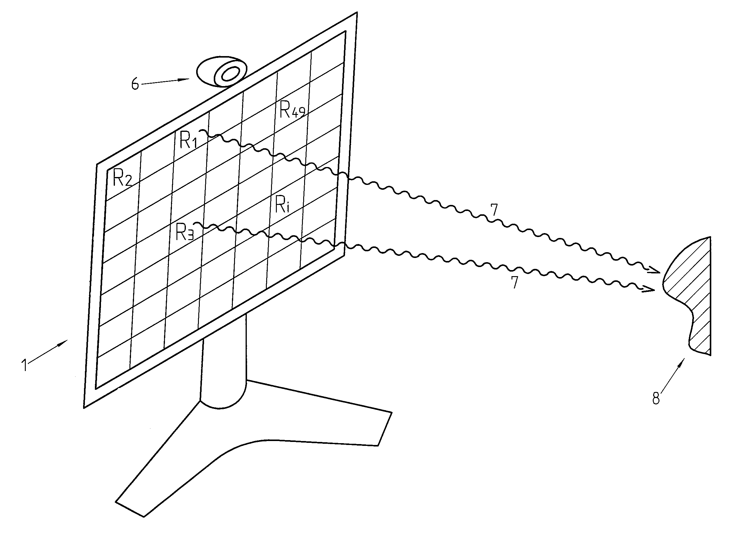
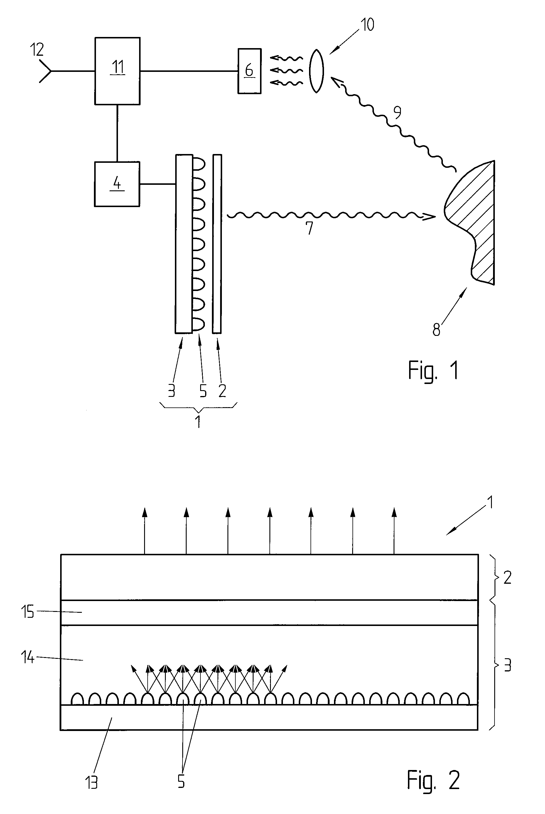
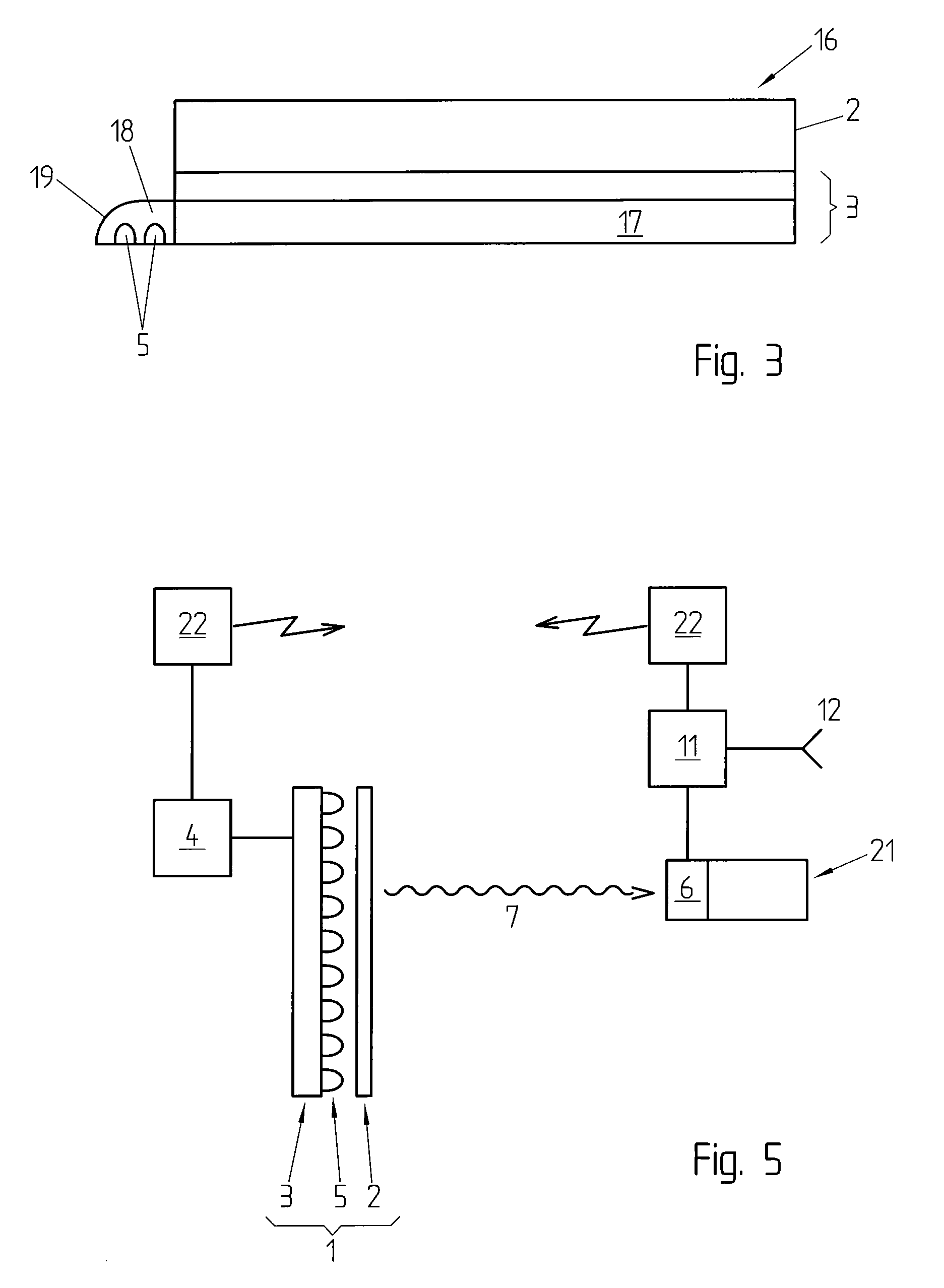
[0025]FIG. 1 illustrates an example of realization of an imaging system according to an embodiment of the present invention. The imaging system includes a backlit display 1 comprising an electronic display 2, such as an LCD display, and a backlight assembly 3, placed behind the electronic display 2 and comprising an array of LEDs 5 for illuminating the electronic display 2. The imaging system also comprises a backlighting driver 4 for adjusting the amount of current provided to the backlight assembly 3 and the corresponding light intensity of the LEDs 5; and a photon sensor 6 or array of sensors, placed, in this example, on one side of the electronic display 2 or possibly behind. In the present invention, a light signal 7 is emitted by a photon emitter, here the backlit display 1. The emitted light signal 7 reaches an object 8 and the reflected light signal 9 travels back to the photon sensor 6. The emitted light signal is described in more details below. An imaging lens 10 can be p...


PUM


Abstract

The present invention concerns a time-of-flight based imaging system having a photon emitter used as an illumination source, a photon sensor, and an electronic system for delivering a signal depending on the reception time of photons by said photon detector. The electronic display is used as the photonic source.

Description

[0001]The present application is a continuation of international application WO08EP054450 filed on Apr. 11, 2008, the content of which being hereby incorporated by reference.FIELD OF THE INVENTION[0002]The present invention concerns a time-of-flight based imaging system, more particularly a low power, versatile and low cost time-of-flight based imaging system.DESCRIPTION OF RELATED ART[0003]The emergence of novel potentially high-volume applications for three-dimensional (3D) optical imaging has generated renewed interest in such devices. These applications include land and sea surveyors, virtual keyboards, face recognition systems, non-ionising medical tomographic imagers, stage and choreography analysis tools, etc. A new generation of solid-state imagers has been designed to address concerns of compactness and speed. However, power, safety, and cost limitations still exist.[0004]Current solid-state 3D optical imaging is based on three main techniques: triangulation, interferometry...

Claims


Application Information

Patent Timeline
Patent Type & Authority Patents(United States)
IPC IPC(8): H04N7/18G01S7/481G01S17/89G06F3/042G01S17/894
CPCG06F3/0421G01S7/4814G01S17/89G01S17/894G01S7/497
Inventor NICLASS, CRISTIANOCHARBON, EDOARDONOLAN, JULIAN
Owner ECOLE POLYTECHNIQUE FEDERALE DE LAUSANNE (EPFL)
Why Eureka
Try Eureka