
Optical printer head and image forming apparatus

a technology which is applied in the direction of electrographic process, electrographic process using charge pattern, instruments, etc., can solve the problems of high cost of image forming apparatus and printer head, and achieve the effect of preventing dimming and low cos

Active Publication Date: 2014-08-26
OKI ELECTRIC IND CO LTD
View PDF15 Cites 1 Cited by
  • Summary
  • Abstract
  • Description
  • Claims
  • Application Information

AI Technical Summary

Benefits of technology

The resin layer effectively prevents light dimming at the lens, maintaining image quality without the need for expensive photo-catalyst layers, thus reducing costs and ensuring clear images in optical printer heads and image forming apparatuses.

Problems solved by technology

When, however, a photo-catalyst layer is employed to prevent the dimming of light at the lens, an optical printer head, and an image forming apparatus that employs this optical printer head, becomes expensive.

Method used


Image

  • Optical printer head and image forming apparatus
  • Optical printer head and image forming apparatus
  • Optical printer head and image forming apparatus

Examples


Embodiment Construction

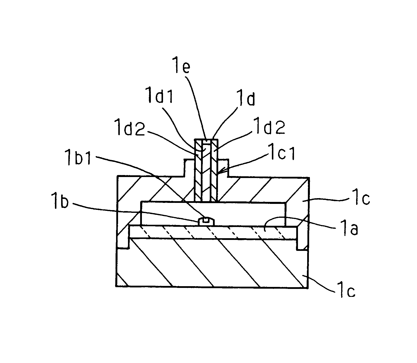
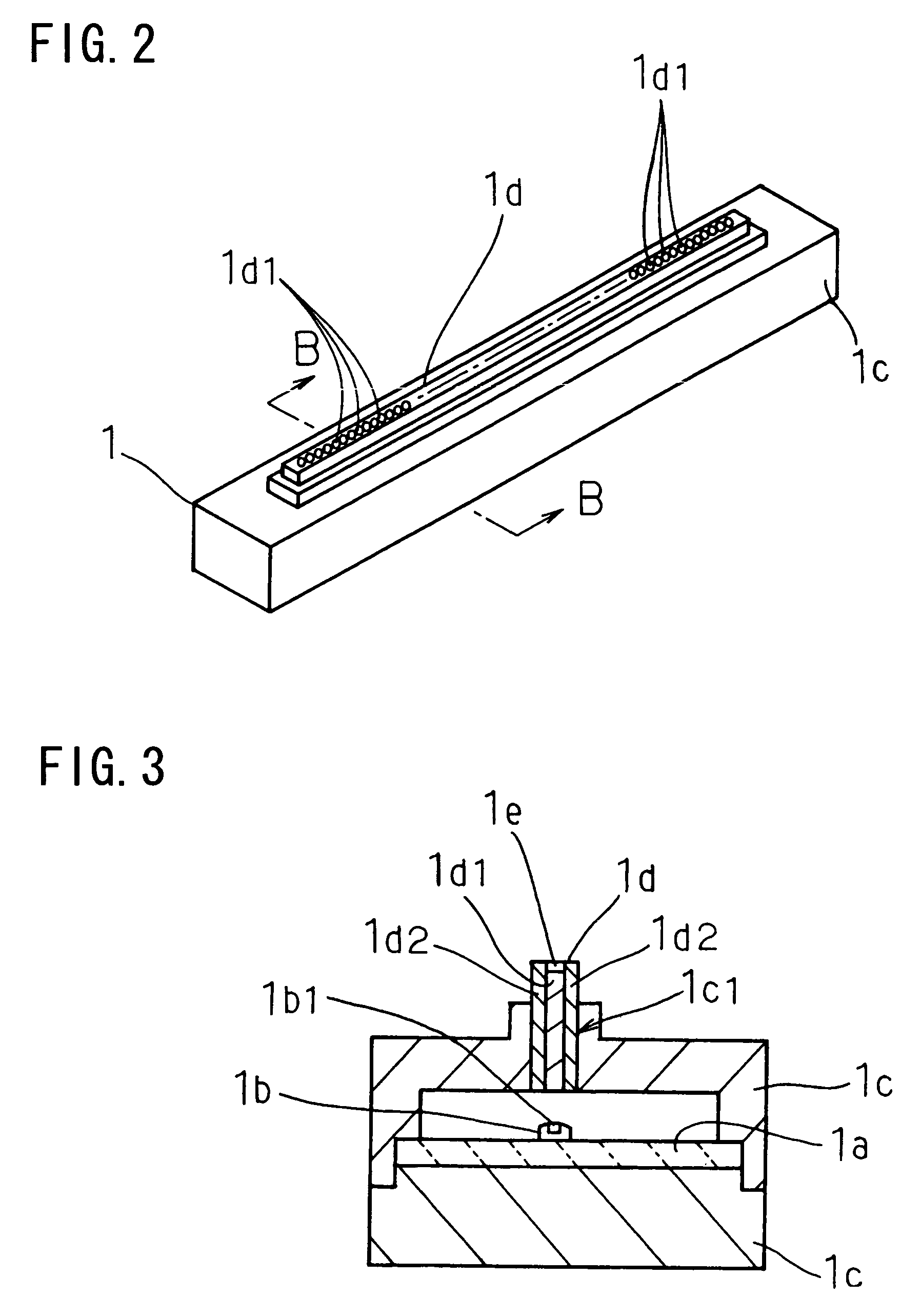
[0042]An image forming apparatus according to one embodiment of the present invention will now be described while referring to the accompanying drawings.

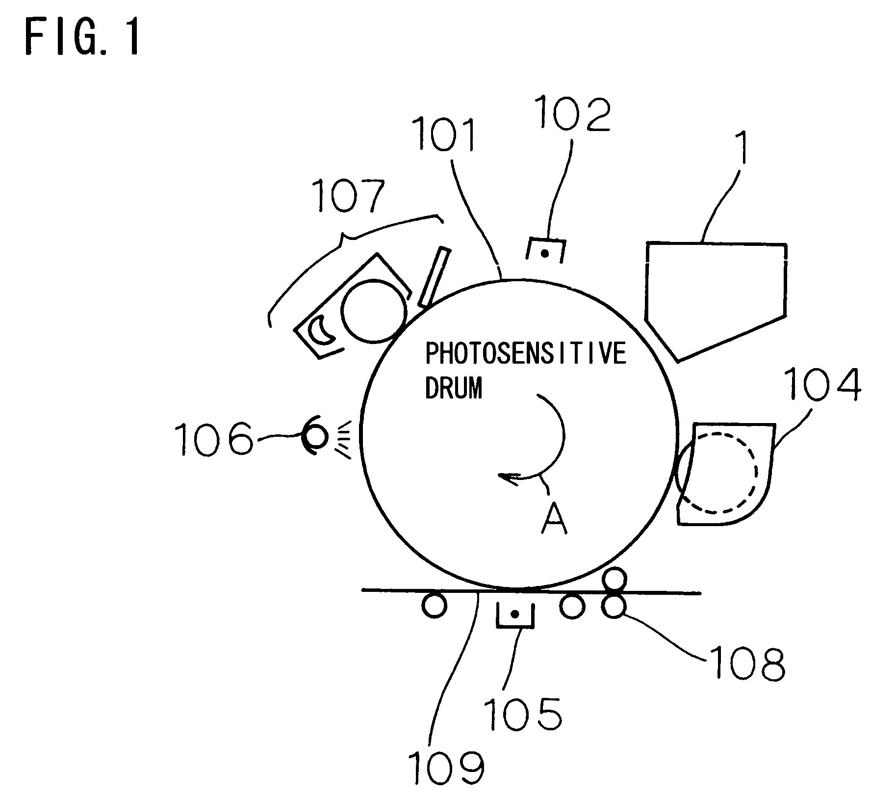
[0043]FIG. 1 is a schematic diagram showing the configuration of an electrophotographic printer according to the embodiment. In FIG. 1, the same reference numerals as used in FIG. 4 are employed to denote corresponding components.

[0044]In FIG. 1, the electrophotographic printer includes an LED array head 1, a photosensitive drum 101, a charging device 102, a developing device 104, a transfer device 105, a charge elimination device 106, a cleaning device 107 and a sheet feeding device 108.

[0045]The electrophotographic printer is an example of an image forming apparatus, the LED array head 1 is an example of an optical printer head, and the photosensitive drum 101 is an example of a photosensitive member.

[0046]The LED array head 1 emits light to irradiate the surface of the photosensitive drum 101 to which a charge, having a predeterm...


PUM


Abstract

An optical printer head has an array of lenses that project light emitted by an array of LEDs onto a charged photosensitive drum to form a latent image on the drum surface. A resin film adhered to the exposed surfaces of the lenses prevents chemical reaction between nitric acid, formed as a consequence of ozone produced during electric charging of the photosensitive drum, and alkali components on the surfaces of the lenses thereby preventing clouding of the lens surfaces and dimming of the projected light. The resin film has a thickness of 10 to 100 microns and may be formed of polyvinyl chloride, polyethylene terephthalate or polymethyl meta acrylate.

Description

BACKGROUND OF THE INVENTION[0001]1. Field of the Invention[0002]The present invention relates to an optical printer head and an image forming apparatus.[0003]2. Related Background Art[0004]Conventionally, an optical printer head, such as an LED array head, is employed as exposure means for an image forming apparatus, such as an electrophotographic printer.[0005]FIG. 4 is a schematic diagram showing the configuration of an electrophotographic printer.[0006]In FIG. 4, the electrophotographic printer includes a photosensitive drum 101, a charging device 102, an LED array head 103, a developing device 104, a transfer device 105, a charge elimination device 106, a cleaning device 107 and a sheet feeding device 108.[0007]When the photosensitive drum 101 is exposed to light after a charge has been placed on the surface of the photosensitive drum 101, a latent image, consonant with the light, is formed on the surface. In this case, the photosensitive drum 101 is rotated in a direction indic...

Claims


Application Information

Patent Timeline
Patent Type & Authority Patents(United States)
IPC IPC(8): H01L27/15
CPCB41J2/451G03G15/02
Inventor UTSUGI, KAZUYASUZUKI, TOSHIKAZU
Owner OKI ELECTRIC IND CO LTD
Learn More