
Method and apparatus for curing ultraviolet-curing resin

a technology of ultraviolet-curing resin and curing method, which is applied in the field of methods and apparatuses for curing ultraviolet-curing resin, can solve the problems of insufficient irradiation dosage and uneconomical ultraviolet-irradiating lamps of normal use, and achieve the reduction of the ultraviolet-ray transmission coefficient of tubular members 1 and the operation ratio of ultraviolet-irradiating apparatus. , the effect of preventing the decline of the ultraviolet-ray transmission coefficient of tubular

Inactive Publication Date: 2002-06-04
SUMITOMO ELECTRIC IND LTD
View PDF7 Cites 5 Cited by
  • Summary
  • Abstract
  • Description
  • Claims
  • Application Information

AI Technical Summary

Benefits of technology

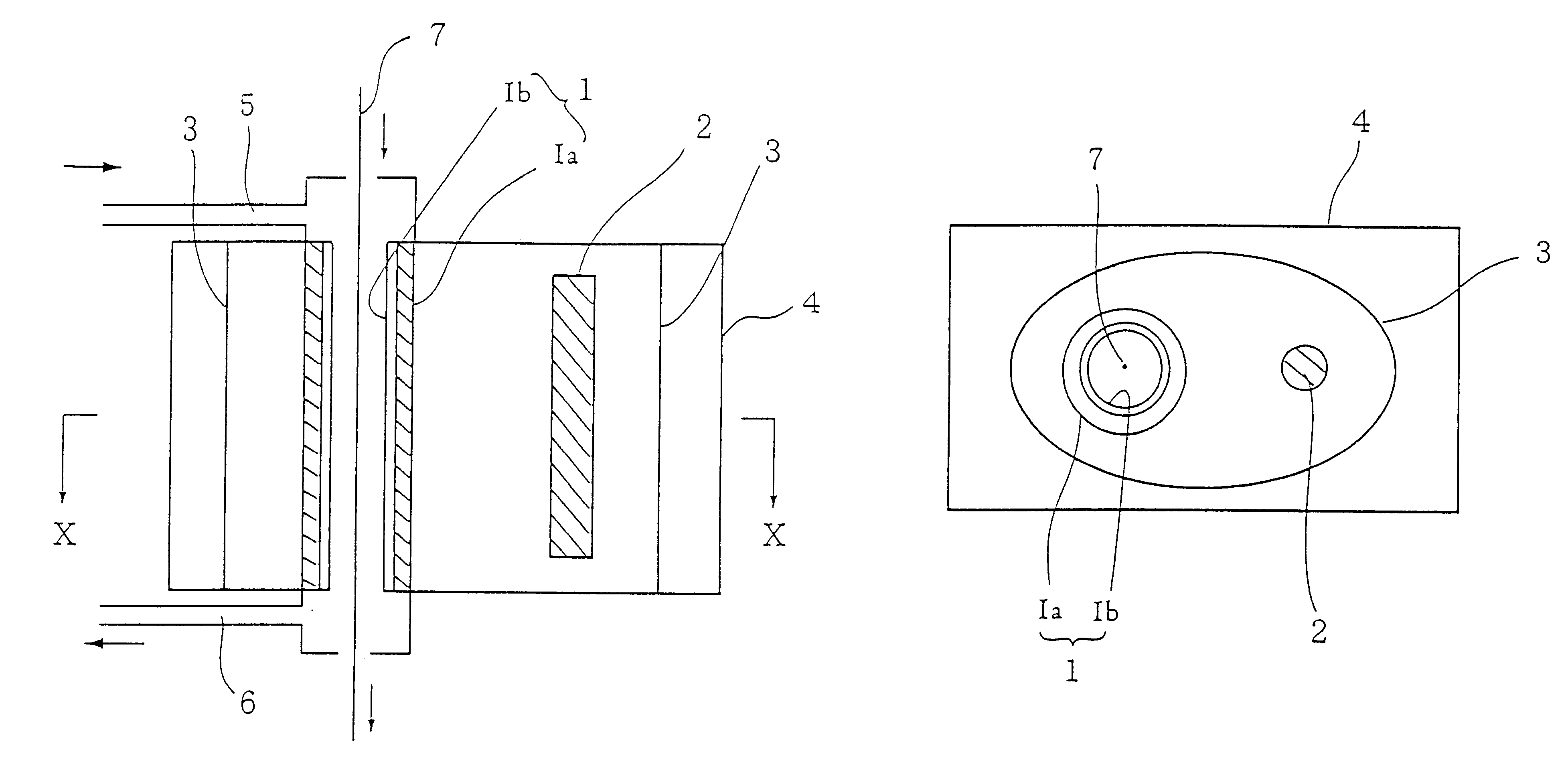
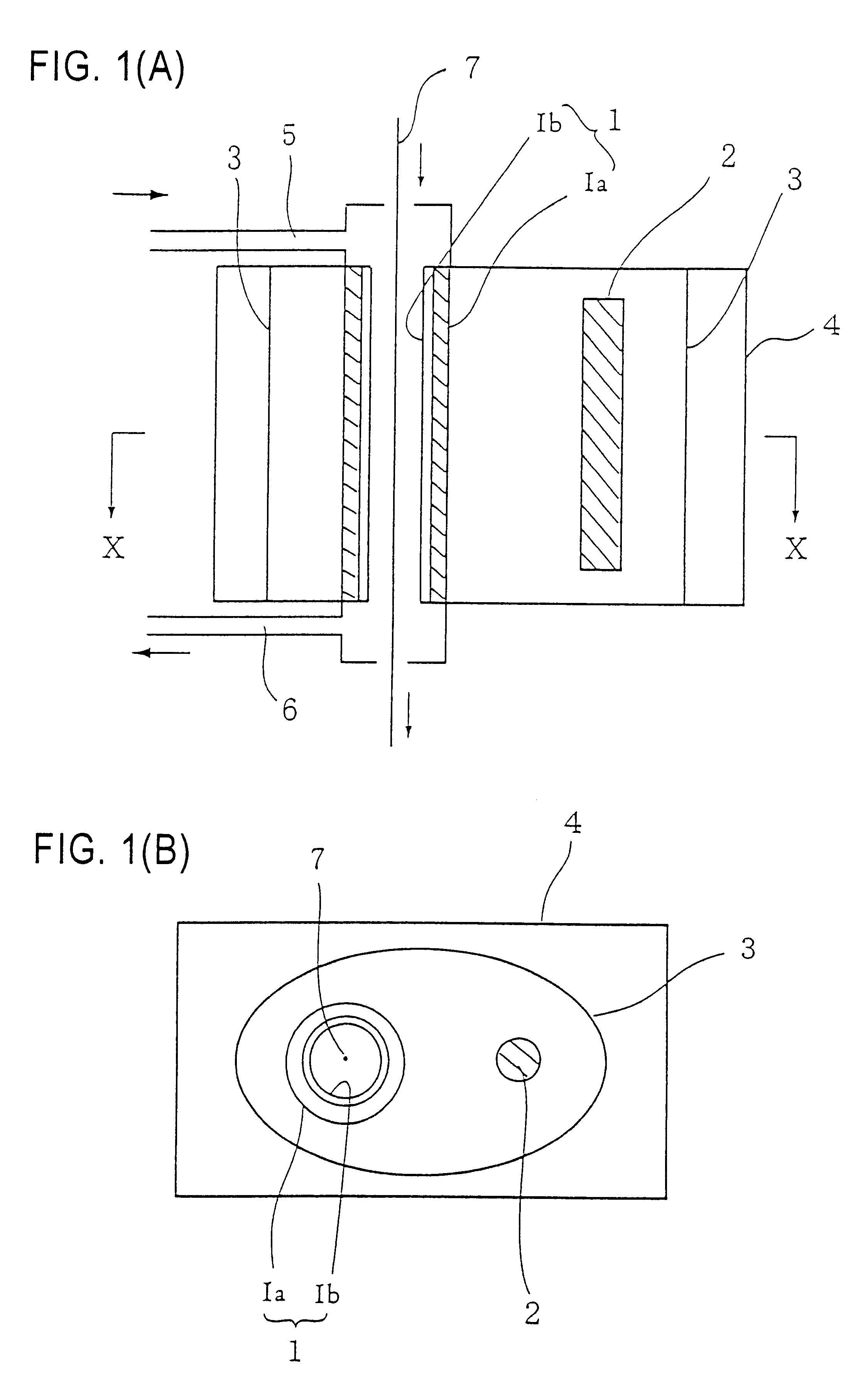
The frequency of need to exchange ultraviolet-transmitting tubular members of the curing apparatus can be decreased because dimming of the ultraviolet-transmitting tubular member can be prevented by the above-described methods of the present invention, that is, by coating the inner surface of the ultraviolet-transmitting tubular member with titanium dioxide and controlling the inner atmosphere of the ultraviolet-transmitting tubular member to a designed oxygen concentration. Further, because a single operation of coating an ultraviolet-curing resin can be continued for a longer period of time, a longer linear body can be obtained, which could not have been obtained conventionally.
By adjusting each of the above elements, it is possible to control the oxygen concentration inside the ultraviolet-transmitting tubular member to a desired value.

Problems solved by technology

Further, it also became clear that although dimming components did not adhere quite so much, a sufficient irradiation dosage could not be obtained from an ultraviolet irradiating lamp of normal usage and occasionally the ultraviolet-curing resin was undercured.
In order to obtain an ultraviolet rays dose sufficient to perform curing of the ultraviolet-curing resin, there is also a method using a high-output ultraviolet irradiating lamp, but it is not economical.

Method used


Image

  • Method and apparatus for curing ultraviolet-curing resin
  • Method and apparatus for curing ultraviolet-curing resin
  • Method and apparatus for curing ultraviolet-curing resin

Examples


Embodiment Construction

The example is described in further detail in the following. The present invention is not limited to this example.

1. Titanium dioxide coating

Powdered titanium dioxide (TiO.sub.2) having particle diameters of 30 nm or smaller was mixed with polysilazane (--(SiH.sub.2 NH--) at a ratio by weight of 1:1 and diluted with xylene. This liquid mixture was poured into a quartz tube to coat the inner surface thereof.

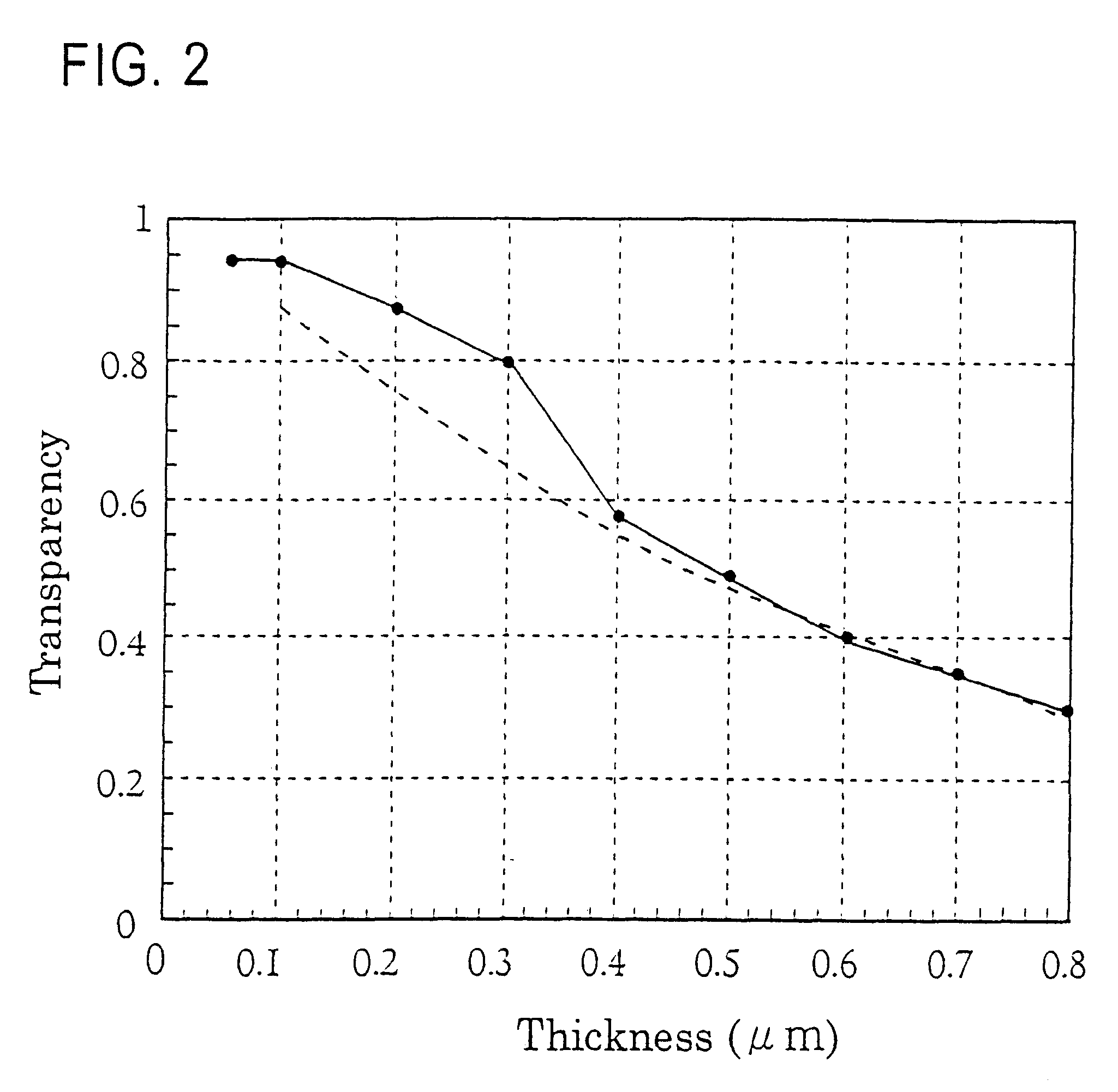
The quartz tube was then calcinated at 450.+-.50.degree. C. to form a coating layer on the inner surface of the quartz tube. The thickness of the coating titanium dioxide layer was adjusted with the degree of dilution with xylene.

2. Optical fiber coating

Using the optical fiber manufacturing apparatus shown in FIG. 5, and optical fiber 30 was coated with ultraviolet-curing resin (a urethane acrylate resin) with a coating device 34, and the ultraviolet-curing resin was cured with a curing device 21. The degree of viscosity of the ultraviolet-curing resin was 1000-2000 cp at 40.degre...


PUM

PropertyMeasurementUnit
Fractionaaaaaaaaaa
Diameteraaaaaaaaaa
Fractionaaaaaaaaaa

Abstract

The amount of dimming components originating in an ultraviolet-curing resin and adhering to a quartz tube is reduced, and a decline in the ultraviolet transmittance is prevented, during ultraviolet-curing of a resin coated on a liner body through an ultraviolet-transmitting tubular member placed inside a curing apparatus and of curing ultraviolet-curing resin by irradiating ultraviolet rays from outside the ultraviolet-transmitting tubular member. Embodiments include coating the inner surface of the ultraviolet-transmitting tubular member with titanium and employing an atmosphere of lover 0.1% oxygen.

Description

This application is a 371 of PCT / JP99 / 03128, filed on Jun. 10, 1999.The present invention relates to a method for curing ultraviolet-curing resin coated on a streaked substance and an ultraviolet curing apparatus used in the method.Methods in which an ultraviolet-curing resin is coated on a linear body such as an optical fiber, a copper wire, a fiber thread, or on a linear body in which a plurality of linear bodies are bundled together or arranged parallel to each other, and is then cured by irradiation of ultraviolet rays, are widely used as methods for coating linear body.The method disclosed in Japanese Patent Publication No. 6-84015 can be given as an example. To explain this method with reference to FIG. 9, a quartz tube 38 is placed inside a curing apparatus 21 as a tubular member for transmitting ultraviolet rays (hereinafter called "ultraviolet-transmitting tubular member"), and a linear body 41 coated with ultraviolet-curing resin is passed through the quartz tube 38, and t...

Claims


Application Information

Patent Timeline
IPC IPC(8): B05D3/06C03C25/12B05C3/02B05C3/12B05C9/14C08F2/48
CPCC03C25/12B05D3/067B05C3/12B05C9/14B05D2256/00
Inventor KUWAHARA, KAZUYANAGAYAMA, KATSUYATSUCHIYA, ICHIRO
Owner SUMITOMO ELECTRIC IND LTD
Learn More