
High frequency mixer with tunable dynamic range

a mixer and dynamic range technology, applied in the field of high frequency mixers, can solve the problems of high transconductance, high conversion gain, undesirable characteristics or disadvantages of mixer types, etc., and achieve the effect of reducing noise and distortion in the signal output and low nois

Inactive Publication Date: 2014-08-26
AVAGO TECH INT SALES PTE LTD
View PDF22 Cites 1 Cited by
  • Summary
  • Abstract
  • Description
  • Claims
  • Application Information

AI Technical Summary

Benefits of technology

The mixer achieves improved linearity and reduced noise, enabling low noise and high-speed performance suitable for multi-band applications with adjustable characteristics for varying RF frequencies, enhancing signal quality and flexibility in receiver architectures.

Problems solved by technology

This type of mixer suffers from some undesirable characteristics or disadvantages.
Gilbert cells provide a low noise figure, but at the expense of a very low linearity, which figure, can be undesirable in some applications.
Another disadvantage is that, when the input transistors 12a and 12b that receive the RF signal are biased at high current, this results in high transconductance and thus high conversion gain.
This, in turn, disturbs the switching action of those devices 14a-d, which gives rise to distortion and noise.
Another disadvantage is that the noise performance of the Gilbert cell mixer at low frequencies is dominated by the noise that arises due to switching action at the devices 14a-d which receive the LO signal.
NMOS switching devices operating at high bias currents, and thus high gate-to-source voltage, exhibit increased output noise.
Low noise performance, especially at low frequencies, e.g., at the output of a down-converting mixer, is very critical in receiver architectures, especially in direct conversion architectures, so that the prior art designs may be undesirable in many applications.

Method used


Image

  • High frequency mixer with tunable dynamic range
  • High frequency mixer with tunable dynamic range
  • High frequency mixer with tunable dynamic range

Examples


Embodiment Construction

[0018]The present invention relates to a high frequency mixer with a tunable dynamic range. The following description is presented to enable one of ordinary skill in the art to make and use the invention and is provided in the context of a patent application and its requirements. Various modifications to the preferred embodiment and the generic principles and features described herein will be readily apparent to those skilled in the art. Thus, the present invention is not intended to be limited to the embodiments shown but is to be accorded the widest scope consistent with the principles and features described herein.

[0019]Embodiments and examples of the present invention are described below. While particular applications and methods are explained, it should be understood that the present invention can be used in a wide variety of other applications and with other techniques within the scope of the present invention.

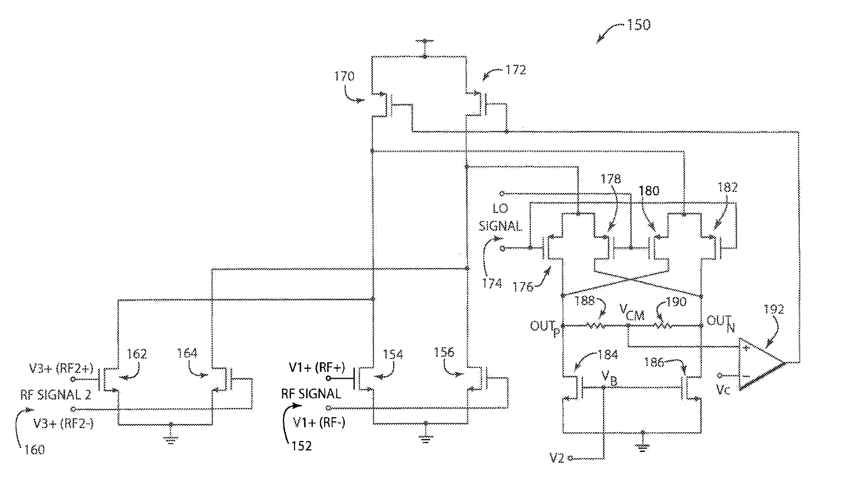
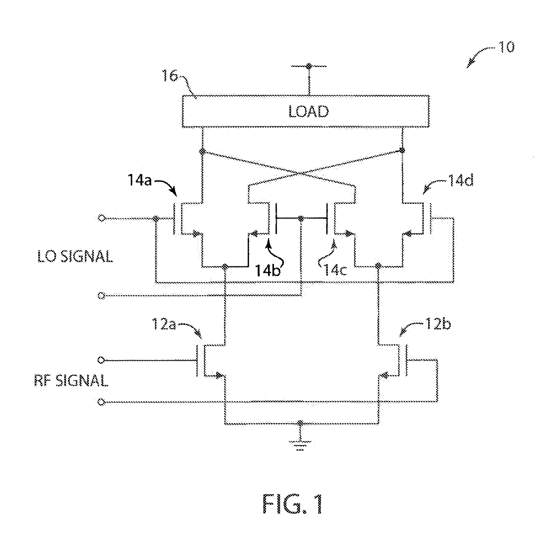
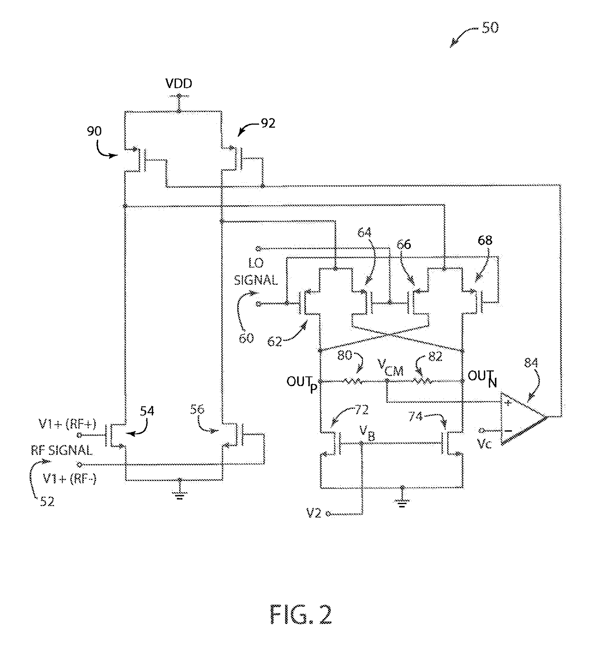
[0020]The present invention provides a mixer suitable for high-freq...


PUM


Abstract

A high frequency mixer with a tunable dynamic range is disclosed. One embodiment provides a mixer apparatus including multiple first transistors at an input branch that receive a differential radio frequency (RF) signal, and multiple second transistors at a second branch that receive a differential local oscillator (LO) signal. The second transistors generate an intermediate frequency (IF) differential output signal. The bias current that flows at the input branch and the output branch can be independently adjusted to allow the conversion gain, linearity, or the output noise of the mixer to be controlled.

Description

CROSS REFERENCE TO RELATED APPLICATIONS[0001]The present application is a continuation of U.S. patent application Ser. No. 10 / 623,097, filed Jul. 17, 2003, now abandoned, which claims the benefit of U.S. Provisional Patent Application No. 60 / 396,454, filed Jul. 17, 2002, and entitled, “CMOS RF Mixer with Tunable Dynamic Range and Combined RF Switch.” Each of the above referenced applications is incorporated herein by reference in its entirety.BACKGROUND OF THE INVENTION[0002]1. Field of the Invention[0003]The present invention relates to high frequency mixers, and more particularly to radio frequency mixers used in communication receivers and other devices.[0004]2. Background Art[0005]Analog multipliers or mixers are typically used in a wide range of communication applications to, for example, up-convert a baseband analog or digital signal for ease of transmission, or down-convert a high frequency signal to baseband for ease of signal processing. For example, in a down-conversion sc...

Claims


Application Information

Patent Timeline
Patent Type & Authority Patents(United States)
IPC IPC(8): G06F7/44G06G7/16
CPCH03D7/1491H03D7/1441H03D7/1458H03D2200/0043H04B15/00
Inventor VAVELIDIS, KONSTANTINOS
Owner AVAGO TECH INT SALES PTE LTD
Learn More