Contact mechanism and electromagnetic contactor using same

a contact mechanism and electromagnetic technology, applied in the field of contact mechanisms, can solve problems such as enlarging the entire configuration, and achieve the effect of preventing the movement of the contact and reducing the thrust of the electromagnet driving the movable conta

Active Publication Date: 2014-08-26
FUJI ELECTRIC FA COMPONENTS & SYST CO LTD
View PDF21 Cites 8 Cited by
  • Summary
  • Abstract
  • Description
  • Claims
  • Application Information

AI Technical Summary

Benefits of technology

[0009]Increasing the contact pressure of the contact spring as described above leads to the necessity of increasing a thrust that is generated by an electromagnet driving the movable contact, enlarging the entire configuration. Alternatively, the electromagnetic contactor needs to be combined with a fuse or a circuit breaker that provides a higher current-limiting effect and is excellent in cutoff performance.
[0010]The present invention, therefore, is conceived in view of the unsolved problems of the prior arts described above, and aims to provide a contact mechanism that is capable of, without enlarging the entire configuration thereof, preventing the generation of an electromagnetic repulsion that opens a movable contact upon application of a current, and also provide an electromagnetic contactor that uses this contact mechanism.
[0012]According to this configuration, at least either the fixed contact or the movable contact is shaped into, for example, an L-shape or U-shape so as to generate the Lorentz force that acts against the electromagnetic repulsion in the opening direction, which is generated between the fixed contact and the movable contact upon application of a current. Therefore, the movable contact can be prevented from opening upon application of a large current.
[0020]According to this configuration, the spring force of a contact spring that brings the movable contact into contact with the fixed contact can be reduced by generating the Lorentz force that acts against the electromagnetic repulsion opening the space between the movable contact and the fixed contact upon application of a current to the electromagnetic contactor. Consequently, the thrust of the electromagnet driving the movable contact can be reduced, providing a small electromagnetic contactor.
[0021]The present invention can generate the Lorentz force that acts against an electromagnetic repulsion in an opening direction, which is generated between the fixed contact and the movable contact when a large current is applied to the contact mechanism that has the fixed contact and the movable contact inserted in a current-carrying path. Therefore, the present invention can reliably prevent the movable contact from being opened upon application of a large current, without using a mechanical pressure.

Problems solved by technology

Increasing the contact pressure of the contact spring as described above leads to the necessity of increasing a thrust that is generated by an electromagnet driving the movable contact, enlarging the entire configuration.

Method used


Image

  • Contact mechanism and electromagnetic contactor using same
  • Contact mechanism and electromagnetic contactor using same
  • Contact mechanism and electromagnetic contactor using same

Examples


first embodiment

[0035]Operations of the above-described first embodiment are described next.

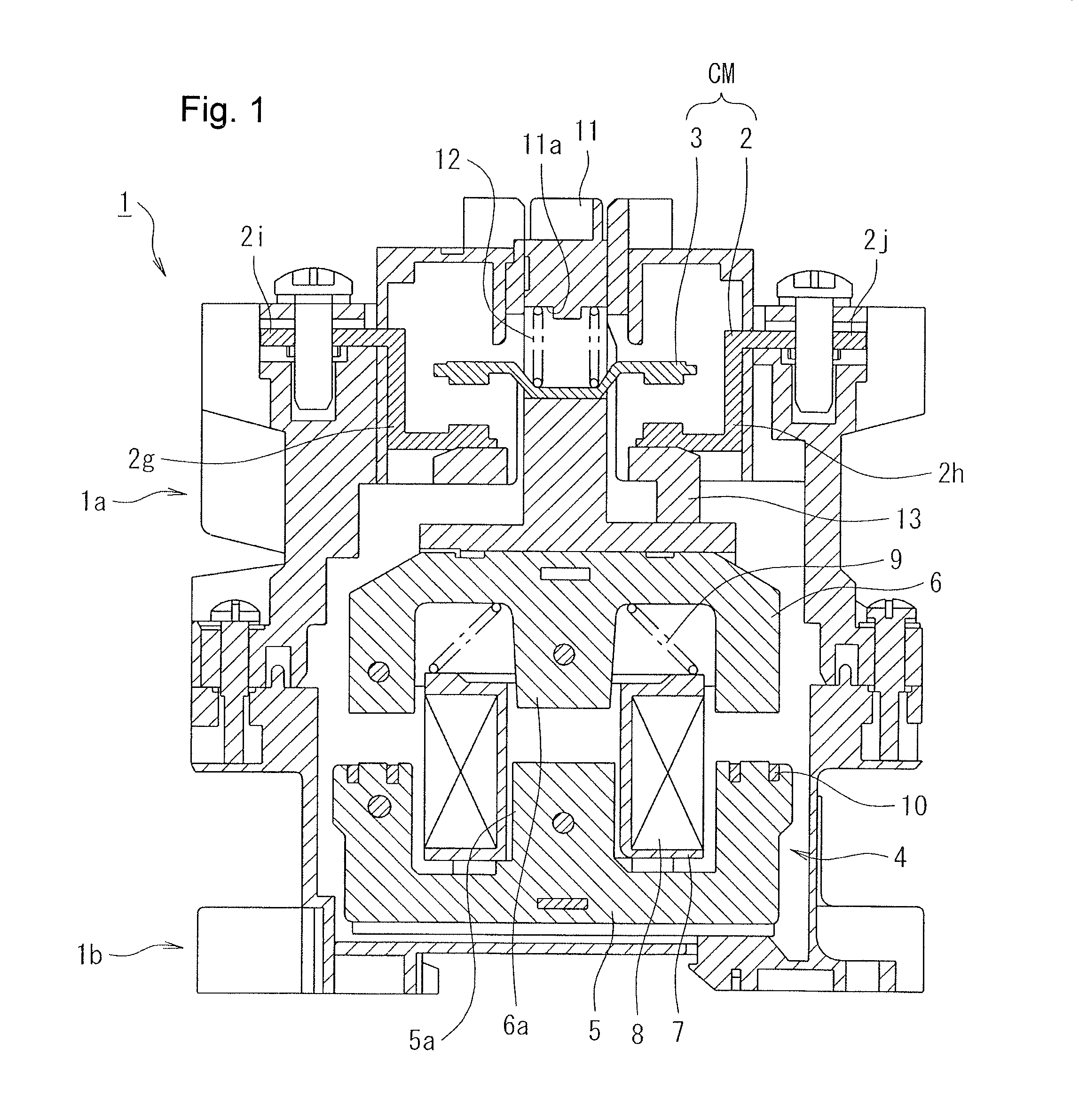
[0036]When the electromagnetic coil 8 of the operating electromagnet 4 is in a non-conductive state, no electromagnetic attracting force is generated between the fixed core 5 and the movable core 6, and, consequently, the movable core 6 is urged by the return spring 9 to move upward away from the fixed core 5. The upper end of the movable core 6 is then abutting with a stopper 13 and accordingly held at a current cutoff position.

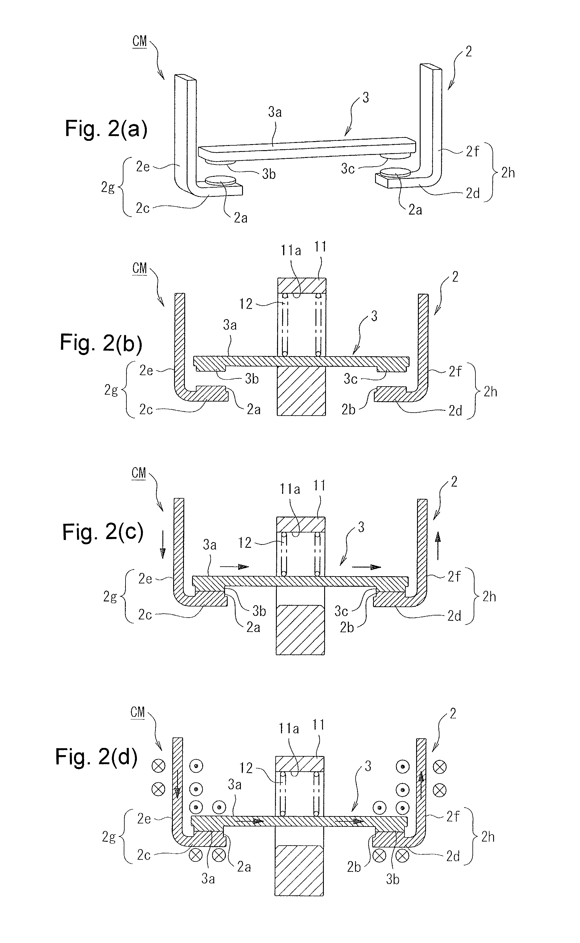
[0037]In a state in which the movable core 6 is held at the current cutoff position, the contact spring 12 brings the movable contact 3 into contact with a bottom part of the insertion hole 11a of the contact holder 11, as shown in FIG. 2(b). In such a state, the movable contact point parts 3b, 3c formed on the ends of the conductive plate 3a of the movable contact 3 separate upward from the fixed contact point parts 2a, 2b of the fixed contact 2, obtaining an opened state of the con...

second embodiment

[0044]Next, the present invention is described with reference to FIGS. 3(a)-3(c).

[0045]In the second embodiment, the Lorentz force acting against the abovementioned electromagnetic repulsion is generated on the back of the movable contact, the electromagnetic repulsion being generated with respect to the fixed contact and the movable contact.

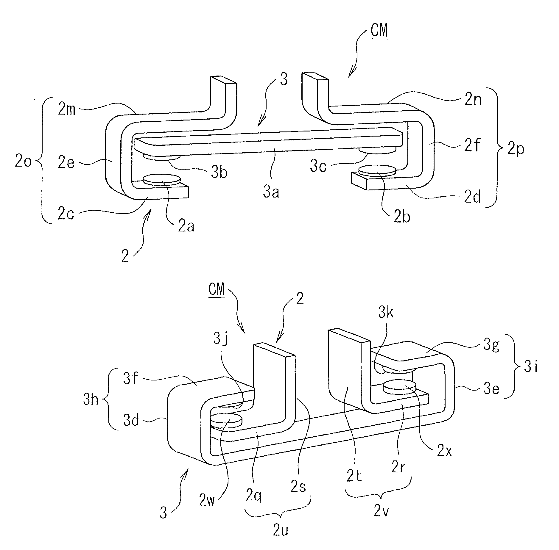
[0046]In other words, the second embodiment has the same configuration as that of the first embodiment, except that the second embodiment has a configuration shown in FIGS. 3(a)-3(c) in which, according to the configuration of the first embodiment shown in FIG. 2(a)-2(d), the second conductive plate parts 2e, 2f of the L-shaped conductive plate parts 2g, 2h of the fixed contact 2 are bent so as to cover upper ends of the end parts of the conductive plate 3a of the movable contact 3 to form third conductive plate parts 2m, 2n parallel to the conductive plate 3a, thereby configuring U-shaped conductive parts 2o, 2p.

[0047]According to the second e...

third embodiment

[0053]Next, the present invention is described with reference to FIGS. 4(a)-4(c).

[0054]Unlike the second embodiment, the third embodiment forms U-shaped folded parts in the movable contact.

[0055]In other words, in the third embodiment, U-shaped folded parts 3h, 3i that are folded above the conductive plate 3a are formed by first conductive plate parts 3d, 3e extending upward from the ends of the conductive plate 3a of the movable contact 3 and second conductive plate parts 3f, 3g that extend inward from upper ends of the first conductive plate parts 3d, 3e, as shown in FIGS. 4(a) to 4(c). Movable contact point parts 3j, 3k are formed on lower surfaces of tip ends of the second conductive plate parts 3f, 3g of these U-shaped folded parts 3h, 3i.

[0056]Furthermore, in an opened state of the contact mechanism CM, the fixed contact 2 has L-shaped conductive plate parts 2u, 2v, which are formed by fourth conductive plate parts 2q, 2r that extend inward facing the conductive plate 3a and ...


PUM


Abstract

The present invention provides a contact mechanism that is capable of, without enlarging the entire configuration thereof, preventing the generation of an electromagnetic repulsion that opens a movable contact upon application of a current, and also provides an electromagnetic contactor that uses this contact mechanism. A contact mechanism (CM) has a fixed contact (2) and a movable contact (3) that are inserted in a current-carrying path. In the contact mechanism (CM), at least either the fixed contact (2) or the movable contact (3) is formed into an L-shape or a U-shape so as to generate a Lorentz force that acts against an electromagnetic repulsion in an opening direction, which is generated between the fixed contact (2) and the movable contact (3) upon application of a current.

Description

RELATED APPLICATIONS[0001]The present application is National Phase of International Application No. PCT / JP2011 / 003376 filed Jun. 14, 2011, and claims priority from Japanese Application No. 2010-168176, filed Jul. 27, 2010.TECHNICAL FIELD[0002]The present invention relates to a contact mechanism having a fixed contact and a movable contact inserted in current path, and to an electromagnetic contactor that uses this contact mechanism, whereby a Lorentz force acting against an electromagnetic repulsion to separate the movable contact from the fixed contact is generated when the electromagnetic contactor is applied with a current.BACKGROUND ART[0003]As a contact mechanism for opening / closing a current path, there has conventionally been proposed a switch, such as a circuit breaker or an electromagnetic contactor. In such a switch that generates an arc when cutting off a current, a fixed contact applied thereto is folded into a U-shape as viewed laterally, and a fixed contact point is f...

Claims


Application Information

Patent Timeline
Patent Type & Authority Patents(United States)
IPC IPC(8): H01H1/54H01H1/00H01H1/06H01H50/54
CPCH01H1/06H01H1/50H01H50/546H01H1/54H01H45/14H01H50/14H01H50/54
Inventor NAKA, YASUHIROTAKAYA, KOUETSUSUZUKI, KENJI
Owner FUJI ELECTRIC FA COMPONENTS & SYST CO LTD
Why Eureka
Try Eureka