Power control device for home appliances

a technology for controlling devices and home appliances, applied in power management, high-level techniques, instruments, etc., can solve problems such as the inability to determine whether an active state is continued or a sleep state is activated, and achieve the effect of low power consumption

Active Publication Date: 2014-08-26
SUN PATENT TRUST
View PDF22 Cites 3 Cited by
  • Summary
  • Abstract
  • Description
  • Claims
  • Application Information

AI Technical Summary

Benefits of technology

[0031]This is also called peak shaving. The total power consumption 1031 may be reduced, for example, by turning off the power supply of a home appliance such as a light or a television, changing the preset temperature of an air-conditioner, changing strong wind mode to power-saving mode of an air-conditioner, or reducing the illuminance of a light.
[0059]According to a communication device of the present invention, low power consumption and real time performance of the communication terminal devices may be achieved at the same time even in applications such as peak suppression with no regularity of data.

Problems solved by technology

However, there may be no regularity of received data depending on application, and thus there is a problem in that whether an active state is continued or a sleep state is activated cannot be determined.

Method used


Image

  • Power control device for home appliances
  • Power control device for home appliances
  • Power control device for home appliances

Examples


embodiment 1

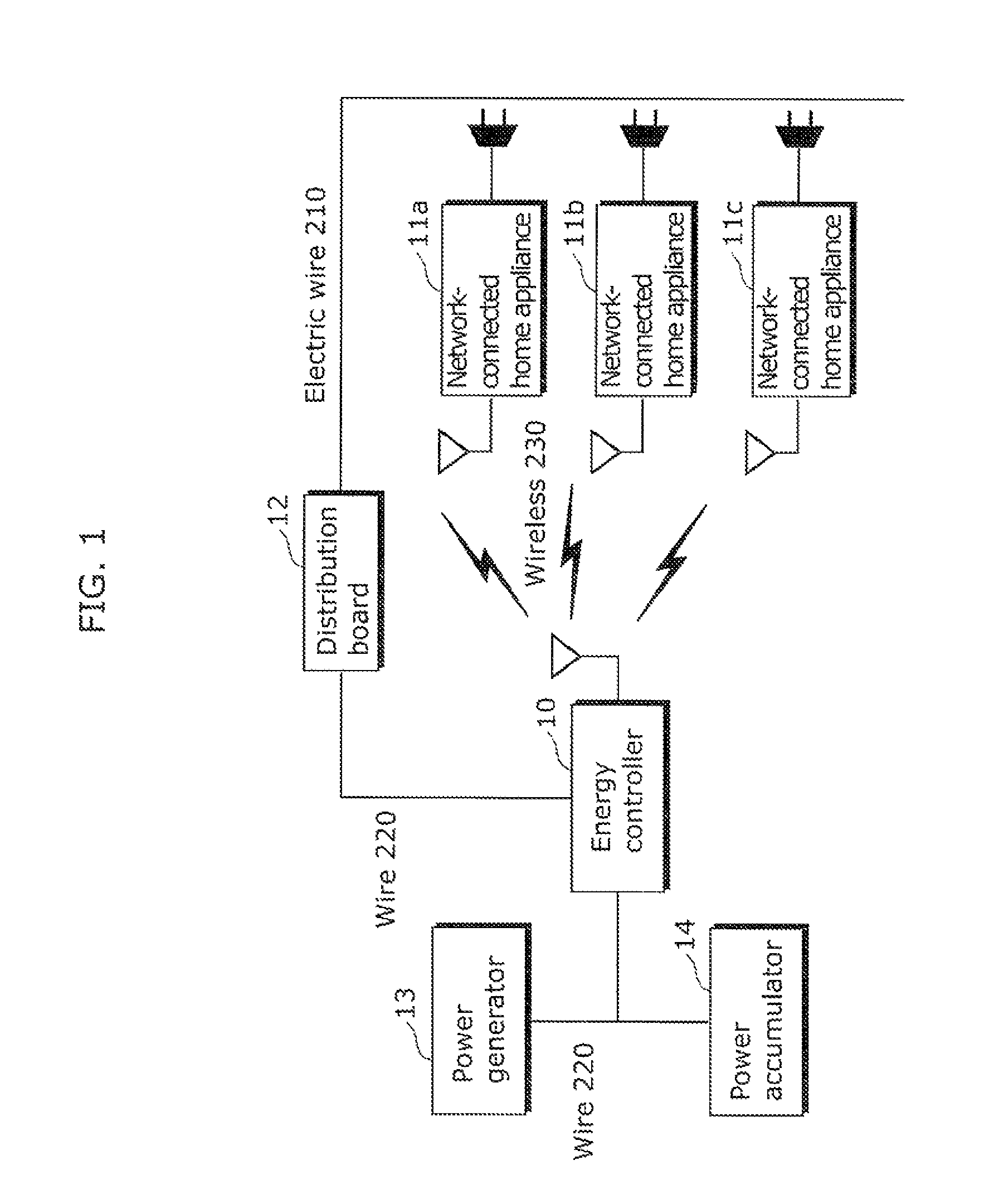
[0109]FIG. 1 is a diagram showing an example of a network configuration of Embodiment 1 of the present invention.

[0110]In FIG. 1, an energy controller 10 is connected to network-connected home appliances 11a, 11b, 11c by a wireless 230. The energy controller 10 is included in “communication device” described in the accompanying claims, and the network-connected home appliances 11a, 11b, 11c are included in “communication terminal device” described in the accompanying claims.

[0111]The wireless 230 may be a connection according to a specific low power wireless which conforms to, for example, the IEEE 802.15.4 standard, the IEEE 802.11 standard, or ARIB (Association of Radio Industries and Businesses).

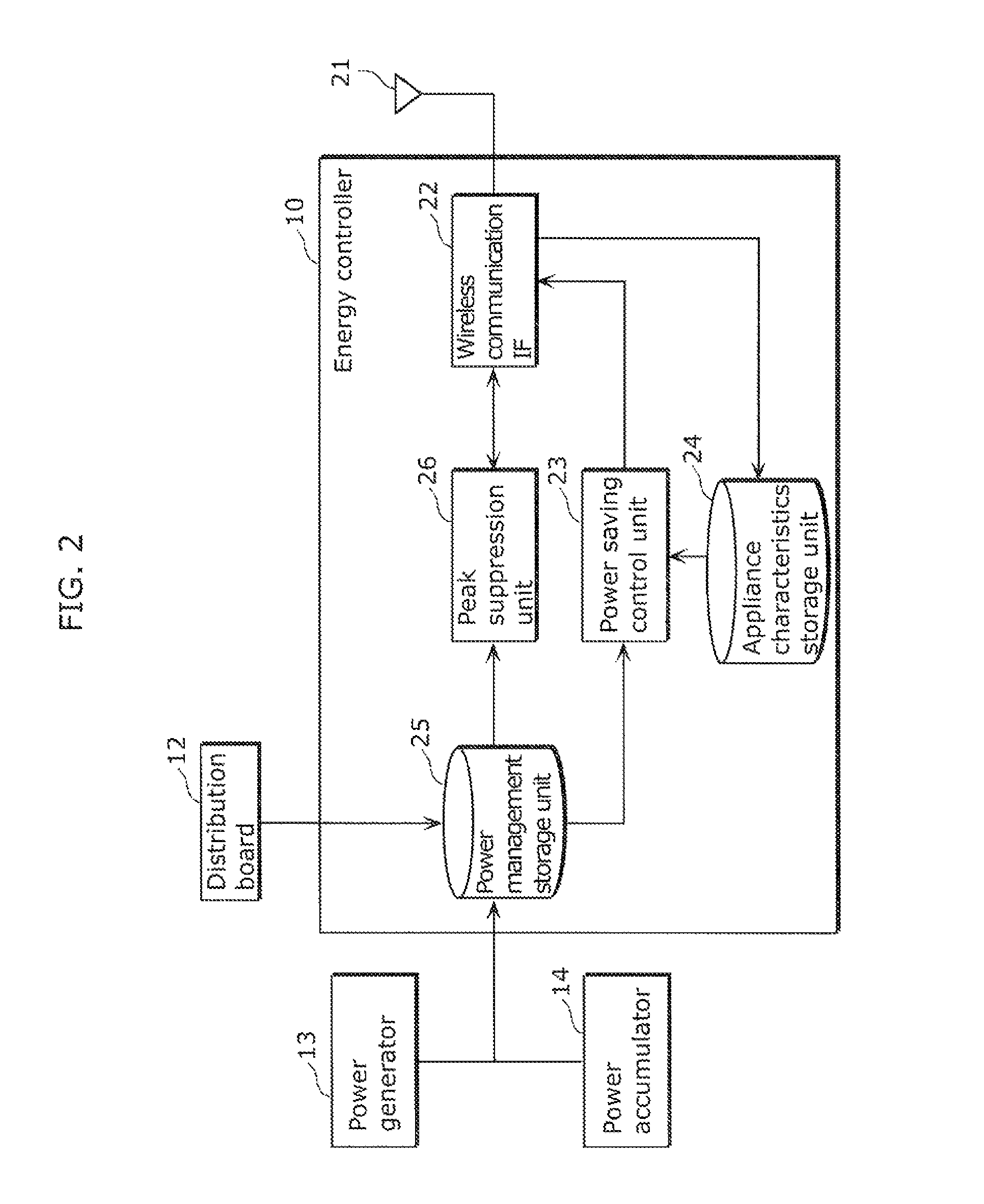
[0112]A distribution board 12 supplies power to all the electric appliances (for example, network-connected home appliance 11a) in a house via an electric wire 210, and can measure the total power consumption in the house. The distribution board 12 is connected to the energy controller 10...

embodiment 2

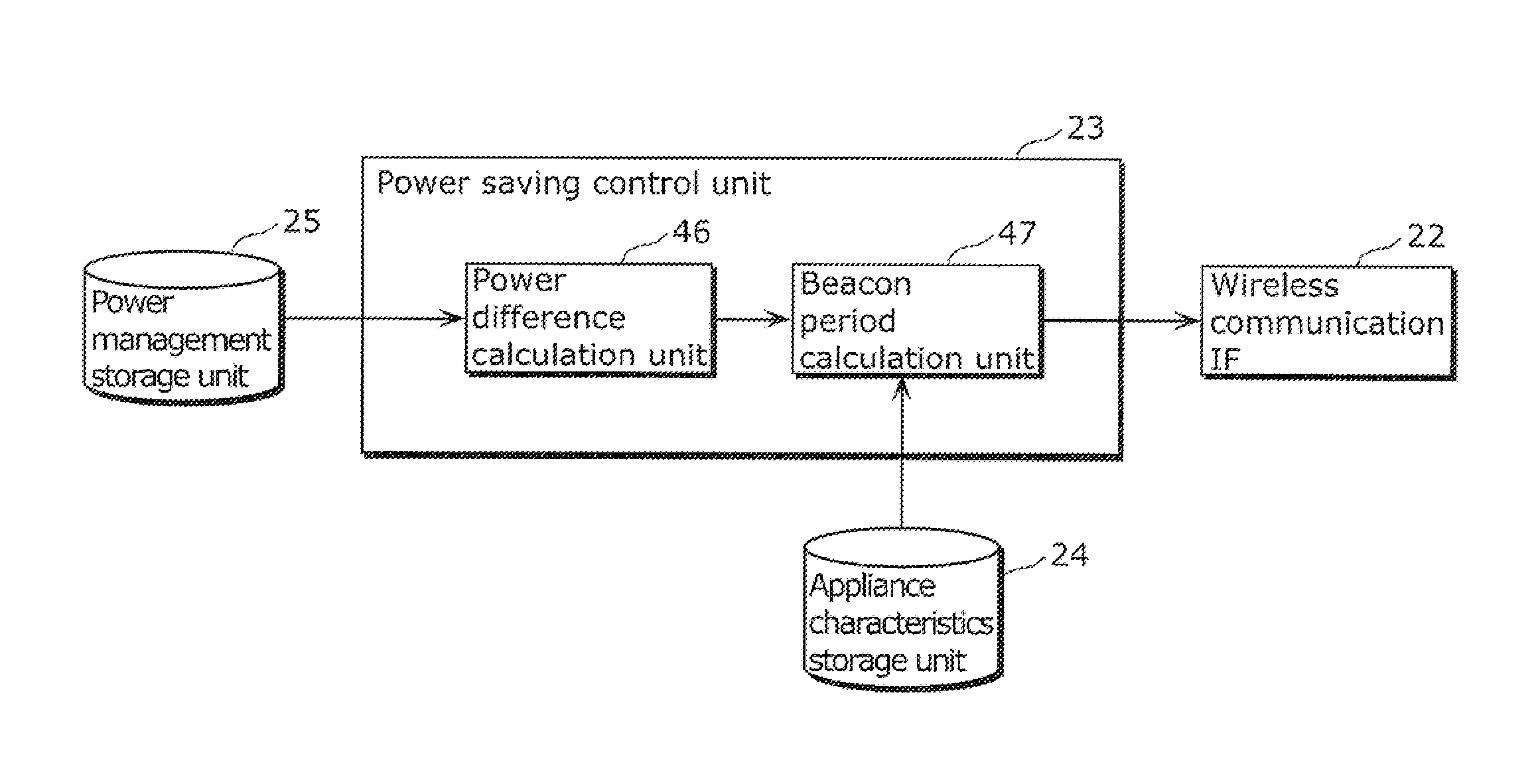
[0208]In the above-described Embodiment 1, a beacon period is calculated based on the power value difference between the available power supply value and the total power consumption value, and the characteristics of the rate of change in the power consumption of the home appliances, and then the beacon period is controlled. Consequently, when the power value difference has a large margin for peak suppression, a longer beacon period is set, and thus low power consumption is achieved, while when the power value difference has a small margin for peak suppression, a shorter beacon period is set, and thus a request for peak suppression can be immediately processed.

[0209]On the other hand, in the present Embodiment 2, after a beacon period is calculated, the beacon period is compared with the beacon value in the stored beacon table and then final beacon period is determined. Consequently, the beacon period can be dynamically changed in a system in which the beacon period is defined by sev...

embodiment 3

[0228]In the above-described Embodiment 1, a beacon period is calculated based on the power value difference between the available power supply value and the total power consumption value, and the characteristics of the rate of change in the power consumption of the home appliances, and then the beacon period is controlled. Consequently, when the power value difference has a large margin for peak suppression, a longer beacon period is set, and thus low power consumption is achieved, while when the power value difference has a small margin for peak suppression, a shorter beacon period is set, and thus a request for peak suppression can be immediately processed.

[0229]On the other hand, in the present Embodiment 3, after a beacon period is calculated, the beacon period is compared with allowable delay times for the applications which are utilized in the wireless network system, and then final beacon period is determined. Consequently, setting of a beacon period exceeding the allowable ...


PUM


Abstract

An energy controller, as a communication device, transmits and receives data by transmitting a signal for establishing transmission and reception of the data to network-connected home appliances. The energy controller includes a power saving control unit that determines a transmission period such that the transmission period during which the signal is transmitted is increased as a power value difference increases, which is a value obtained by subtracting the total power consumption value of a power consumption appliance from available power supply value to the power consumption appliance including the network-connected home appliances; and a wireless communication IF for transmitting the signal containing the information indicating the transmission period to the network-connected home appliances in order to set the network-connected home appliances in an active state with a period according to the transmission period.

Description

BACKGROUND OF INVENTION[0001]1. Technical Field[0002]The present invention relates to a communication device and a communication method in a wireless network system such as WLAN (Wireless Local Area Network) of IEEE (Institute of Electrical and Electronics Engineers) 802.11 standard, or WPAN (Wireless Personal Area Network) of EEE 802.15 standard.[0003]2. Background Art[0004]In recent years, attention is being focused on a network shared by wireless terminals with low power consumption, such as WPAN or a sensor network. As a system like system, there is a system called Active RF (Radio Frequency) which sends a radio signal itself.[0005]FIG. 43 is a diagram showing an example of a conventional wireless network configuration.[0006]In FIG. 43, the wireless network includes a control station 1001 which is a wireless control station, and terminal devices 1002, 1003, 1004 which are a plurality of wireless terminal devices. The control station 1001 periodically broadcasts a beacon packet i...

Claims


Application Information

Patent Timeline
Patent Type & Authority Patents(United States)
IPC IPC(8): H04B7/00
CPCH04W52/0216H02J2003/143H04W52/0258H04W52/0277Y02B60/50Y02B70/3266Y04S20/242H02J2310/14Y02B70/30Y02B70/3225Y04S20/222Y02D30/70
Inventor UKITA, YOSUKENAKAE, HIRONORIHAYASHINO, HIROSHI
Owner SUN PATENT TRUST
Why Eureka
Try Eureka