

Robot hand and robot
- Summary
- Abstract
- Description
- Claims
- Application Information
AI Technical Summary
Benefits of technology
Problems solved by technology
Method used
Image


Examples
first embodiment
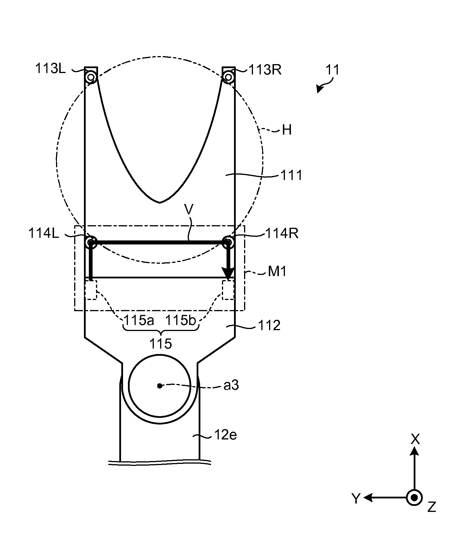
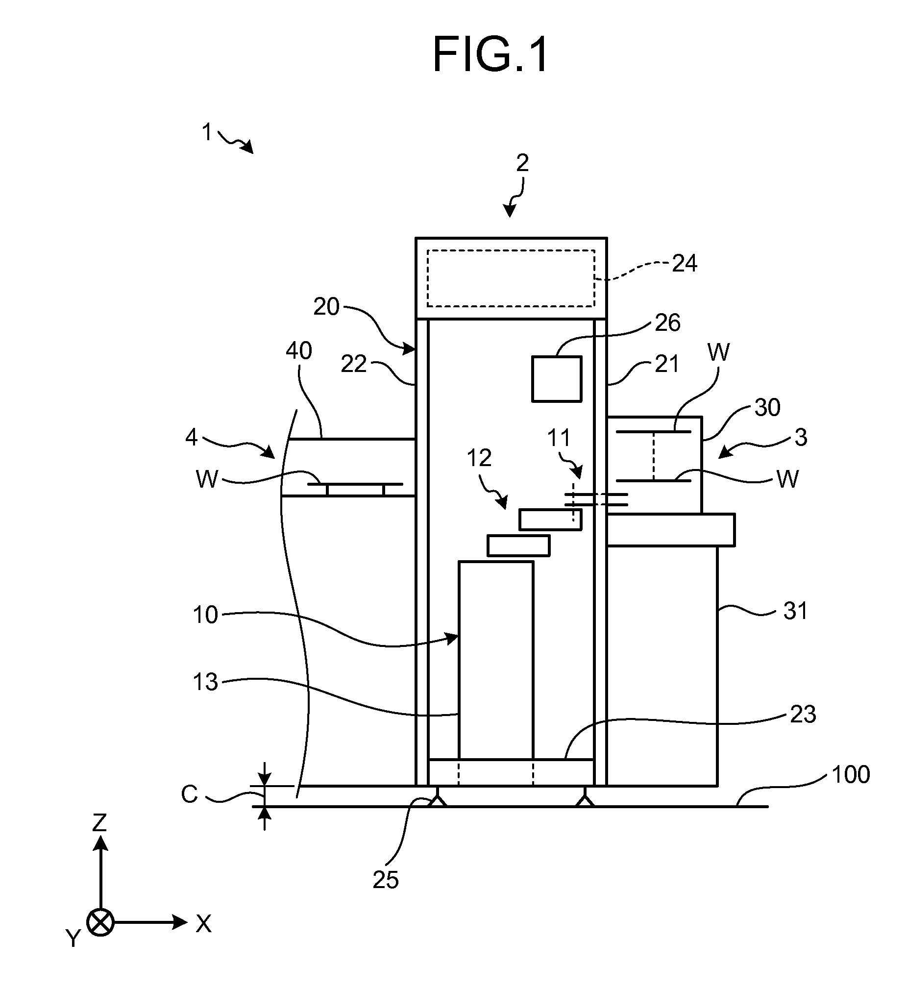
[0024]First, the entire configuration of a carrier system that includes a robot according to an embodiment will be explained with reference to FIG. 1. FIG. 1 is a schematic diagram illustrating the entire configuration of a carrier system 1 that includes a robot according to the embodiment.
[0025]In order to make an explanation understandable, a three-dimensional rectangular coordinate system that includes Z-axis whose vertically upward direction is a positive direction and vertically downward direction (or, vertical direction) is a negative direction is illustrated in FIG. 1. Therefore, a direction taken along an XY plane means a “horizontal direction”. The rectangular coordinate system can be employed in other drawings that are used for the following explanations.
[0026]Hereinafter, a component that is constituted by multiple parts has one reference number for only one part and does not have reference numbers for the other parts in some cases. In this case, one part having a referen...
second embodiment
[0084]FIG. 5A is a diagram illustrating the holding state of wafers W1 and W2. FIGS. 5B to 5D are schematic side views of a hand 11A according to the second embodiment.
[0085]As illustrated in FIG. 5A, the wafer W1 that has high temperature through a heat treatment process can be held on the hand 11 in the curved state in some cases.
[0086]Moreover, as illustrated in FIG. 5A, it is considered that the wafer W2 is held in a slightly diagonal state even if the wafer is not in the curved state.
[0087]Therefore, as illustrated in FIG. 5B, the hand 11A according to the second embodiment includes bottom-side salient portions 114LA and 114RA whose the heights of openings (and the reflecting members therein) are different.
[0088]As a result, because the optical path V surely blocked by the curved wafer W1 or the diagonal wafer W2 can be formed, the presence or absence of a wafer can be surely detected even if the wafer is the curved wafer W1 or the diagonal wafer W2.
[0089]As illustrated in FIG....
third embodiment
[0098]FIG. 6 is a schematic top view of a hand 11B according to the third embodiment. As illustrated in FIG. 6, the third embodiment is different from the above embodiments (the hand 11 and the hand 11A) in that the hand 11B includes a leading-side salient portion 113RA that has a reflecting member (not illustrated).
[0099]The hand 11B makes light from the projector 115a pass through the holding area H at the vicinity of its center P via a bottom-side salient portion 114LD and reach the photoreceiver 115b via the leading-side salient portion 113RA and a bottom-side salient portion 114RD so as to form an optical path V4. That is to say, the optical path V4 passes through the holding area H by way of the bottom-side salient portion 114LD, the leading-side salient portion 113RA, and the bottom-side salient portion 114RD, in this order.
[0100]As a result, even if the wafer W is diagonally held by having slightly different heights at the leading side and the bottom side of the hand 11B, fo...
PUM
 Abstract
Description
Claims
Application Information