Alignment apparatus for X-ray imaging system

a technology of positioning apparatus and x-ray imaging system, which is applied in the field of alignment apparatus for x-ray imaging system, can solve the problems of not being visible to the technician, complicating the alignment task of portable systems, and more difficult to effectively use grids for reducing scattering effects

Active Publication Date: 2014-09-02
CARESTREAM HEALTH INC
View PDF50 Cites 39 Cited by
  • Summary
  • Abstract
  • Description
  • Claims
  • Application Information

AI Technical Summary

Benefits of technology

[0018]An object of the present invention is to advance the art of radiographic imaging by providing exemplary apparatus and methods embodiments to aid in alignment and proper positioning of the radiation source to a radiation receiver. A feature of the present invention is the use of a sensor and detector arrangement that is able to sense distance and positional orientation of the receiver relative to the radiation source. It is an advantage of certain exemplary apparatus and methods embodiments that can allow straightforward retrofitting for existing x-ray apparatus.
[0019]Exemplary apparatus and methods embodiments do not require visibility of the receiver behind the patient for alignment. It is a further advantage of one embodiment that it provides a method that can be adapted for use with a variable SID distance.

Problems solved by technology

Receiver 10, however, because it is portable, may not be visible to the technician once it is positioned behind the patient.
This complicates the alignment task for portable systems, requiring some method for measuring source-to-image distance (SID), tilt angle, and centering, and making it more difficult to use a grid effectively for reducing the effects of scatter.
Because of this added complexity with a portable radiography system, the technician may choose not to use a grid; the result without a grid, however, is typically a lower-quality image.
However, complex mechanical solutions of this type tend to reduce the overall flexibility and portability of these x-ray systems.
Another type of approach, such as that proposed in U.S. Pat. No. 6,422,750 entitled “Digital X-ray Imager Alignment Method” to Kwasnick et al. uses an initial low-exposure pulse for detecting the alignment grid; however, this method would not be suitable for portable imaging conditions where the receiver must be aligned after it is fitted behind the patient.
This arrangement is less than desirable for portable imaging systems that allow a variable SID.
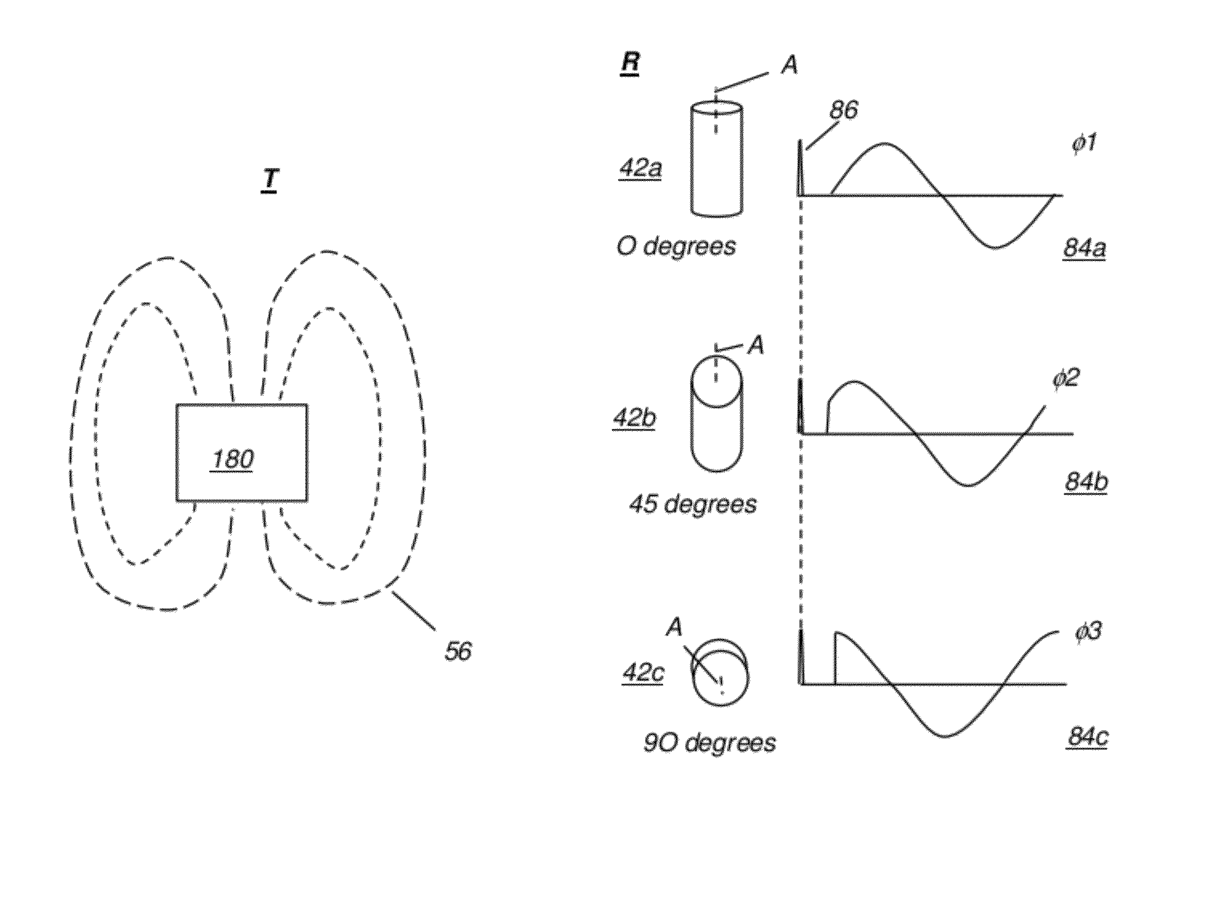
Tilt sensing, as has been conventionally applied and as is used in the device described in U.S. Pat. No. 7,156,553 entitled “Portable Radiation Imaging System and a Radiation Image Detection Device Equipped with an Angular Signal Output Means” to Tanaka et al. and elsewhere, does not provide sufficient information on cassette-to-radiation source orientation, except in the single case where the cassette lies level.
More complex position sensing devices can be used, but can be subject to sampling and accumulated rounding errors that can grow worse over time, requiring frequent resynchronization.
Portable radiography apparatus must be compact and lightweight, which makes the mechanical alignment approach such as that given in the '948 MacMahon disclosure less than desirable.
The constraint to direct line-of-sight alignment reduces the applicability of many types of reflected light based methods to a limited range of imaging situations.
'553 solution would add considerable expense, complexity, weight, and size to existing designs, with limited benefits.
Many less expensive portable radiation imaging units do not have the control logic and motion coordination components that are needed in order to achieve the necessary adjustment.
None of these approaches gives the operator the needed information for making a manual adjustment that is in the right direction for correcting misalignment, particularly where an anti-scatter grid is used.
A related problem is the need to achieve a source-to-image distance (SID) that is well-suited for the image to be obtained and for the grid used.
Conventional alignment solutions do not provide SID information, leaving it to the technician to make separate measurements or to make an approximate SID adjustment.
Moreover, conventional solutions do not provide the technician with tools to help reduce backscatter, caused by misalignment or poor adjustment of the collimator blades.
This type of scatter, while not particularly problematic with other types of radiographic imaging, such as dental and mammographic imaging, can be troublesome with portable radiographic imaging apparatus, since the radiation is directed over a broad area.
Radiation that works past the imaging receiver and any blocking element associated with the receiver can inadvertently be reflected back into the receiver, adversely affecting image quality.
Significantly, none of these conventional solutions described earlier is particularly suitable for retrofit to existing portable radiography systems.
That is, implementing any of these earlier solutions would be prohibitive in practice for all but newly manufactured equipment and could have significant cost impact.
Yet another problem not addressed by many of the above solutions relates to the actual working practices of radiologists and radiological technicians.
'553 application, is not optimal for all types of imaging.
Conventional alignment systems, while they provide for normal incidence of the central ray, do not adapt to assist the technician for adjusting to an oblique angle.

Method used


Image

  • Alignment apparatus for X-ray imaging system
  • Alignment apparatus for X-ray imaging system
  • Alignment apparatus for X-ray imaging system

Examples


Embodiment Construction

[0057]Unlike the limited tilt sensing approaches that have been used in a variety of earlier radiography systems, certain exemplary apparatus and methods embodiments provide a straightforward solution to the problem of radiation source-to-receiver alignment that can be used with a number of x-ray imaging systems.

[0058]In the context of the present disclosure, the term “imaging receiver”, or more simply “receiver”, may include a cassette that has a photostimulable medium, such as a film or phosphor medium, for example, or may include a detector array that records an image according to radiation emitted from the radiation source. A portable receiver is not mechanically coupled to the radiation source, so that it can be easily and conveniently positioned behind the patient.

[0059]As used herein, the term “energizable” indicates a device or set of components that perform an indicated function upon receiving power and, optionally, upon receiving an enabling signal.

[0060]In the context of ...


PUM


Abstract

A method for aligning a radiation source with a portable image receiver in a radiographic imaging system generates a magnetic field with a predetermined field pattern and with a time-varying vector direction at a predetermined frequency from an emitter apparatus that is coupled to the radiation source, wherein the generated magnetic field further comprises a synchronization signal. Sensed signals from the magnetic field are obtained from a sensing apparatus that is coupled to the image receiver, wherein the sensing apparatus comprises three or more sensor elements, wherein at least two of the sensor elements are arranged at different angles relative to each other and are disposed outside the imaging area of the image receiver. An output signal is indicative of an alignment adjustment according to the amplitude and phase of the obtained sensed signals relative to the synchronization signal.

Description

CROSS-REFERENCE TO RELATED APPLICATIONS[0001]This is a 35 U.S.C 111a application that claims the benefit of U.S. Provisional Application Ser. No. 61 / 450,260, filed 8 Mar. 2011, entitled “ALIGNMENT METHOD FOR X-RAY IMAGING,” by Joseph Stagnitto and of U.S. Provisional Application Ser. No. 61 / 553,396, filed 12 Sep. 2011, entitled “ALIGNMENT APPARATUS FOR X-RAY IMAGING SYSTEM” by Joseph Stagnitto et al.FIELD OF THE INVENTION[0002]This invention generally relates to an apparatus for radiation imaging and more particularly relates to a positioning apparatus for providing proper alignment of the radiation source relative to an image detection device for recording a radiation image.BACKGROUND OF THE INVENTION[0003]When an x-ray image is obtained, there is generally an optimal alignment between the radiation source and the two dimensional receiver that records the image data. In most cases, it is preferred that the x-ray source provide radiation in a direction that is perpendicular to the s...

Claims


Application Information

Patent Timeline
Patent Type & Authority Patents(United States)
IPC IPC(8): A61B6/00A61B6/08
CPCA61B6/4291A61B6/4405G03B42/025A61B6/547A61B6/08A61B6/588A61B6/465A61B6/587
Inventor STAGNITTO, JOSEPH E.WANG, XIAOHUILALENA, MICHAEL C.
Owner CARESTREAM HEALTH INC
Why Eureka
Try Eureka