Disconnector for distribution transformers with dielectric liquid

a technology of dielectric liquid and disconnector, which is applied in the direction of protective switch details, protective switch operating/releasing mechanisms, emergency protective circuit arrangements, etc., can solve the problems of short circuit, disconnection of transformer, and high voltage side that does not guarantee that current will stop flowing in the damaged circuit of the transformer, so as to reduce the power-carrying capacity of the network

Active Publication Date: 2014-09-02
HITACHI ENERGY LTD
View PDF6 Cites 2 Cited by
  • Summary
  • Abstract
  • Description
  • Claims
  • Application Information

AI Technical Summary

Benefits of technology

[0013]The advantage of the disconnector according to the invention, provided with a protection in the form of an additional auxiliary contact, connected with a switch located on the low voltage side is that it provides effective disconnection of the transformer from a three-phase distribution network and thus it provides protection of the transformer against explosion as well as protection of the distribution network in case of failures detected on the low voltage side. In the protective system, the control signal is supplied to the low voltage-side switch causing three-phase disconnection from the network also on the LV side. If the disconnection of one transformer working in a distribution network has been due to the failure of the transformer itself, the other transformers in the network and other electric power equipment can continue normal operation. The network can continue supplying electric energy. Only the power-carrying capacity of the network is reduced by the power of the disconnected transformer. The protection on the low voltage side works autonomously and it protects the transformer against the effects of damage to the network on the low voltage side independently of the protection on the high voltage side.

Problems solved by technology

Exceeding the predetermined parameters of oil level or pressure results in shorting of fuses and consequently in the disconnection of the transformer.
In a situation where the transformer is connected in parallel on the secondary circuit side i.e. on the low voltage side with another electric unit, the action of the disconnector mounted on the high voltage side does not guarantee that current will stop flowing in the damaged circuits of the transformer.
The value of current flowing in the damaged circuits of the transformer may be lower than the detection threshold of the disconnector mounted on the high voltage side, which may result in a build-up of the effects of the failure until the transformer explodes.

Method used


Image

  • Disconnector for distribution transformers with dielectric liquid
  • Disconnector for distribution transformers with dielectric liquid
  • Disconnector for distribution transformers with dielectric liquid

Examples


Embodiment Construction

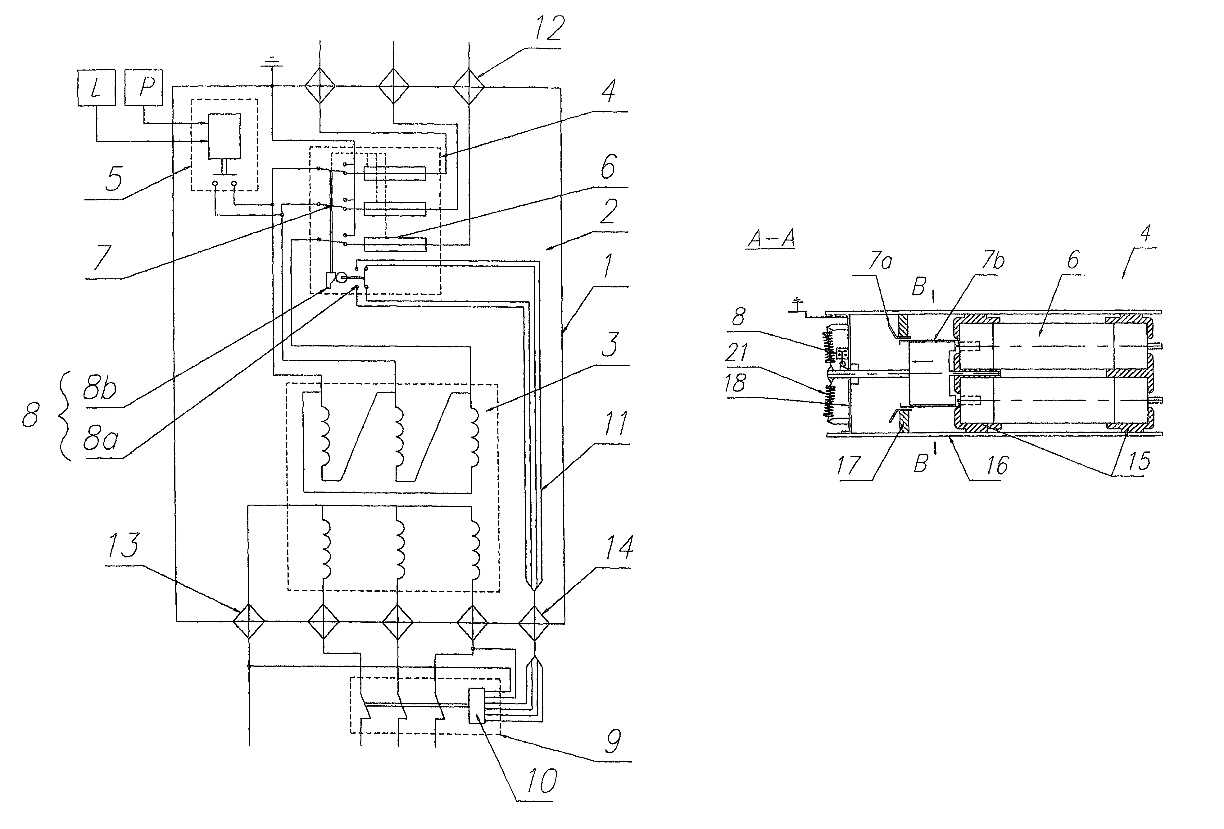
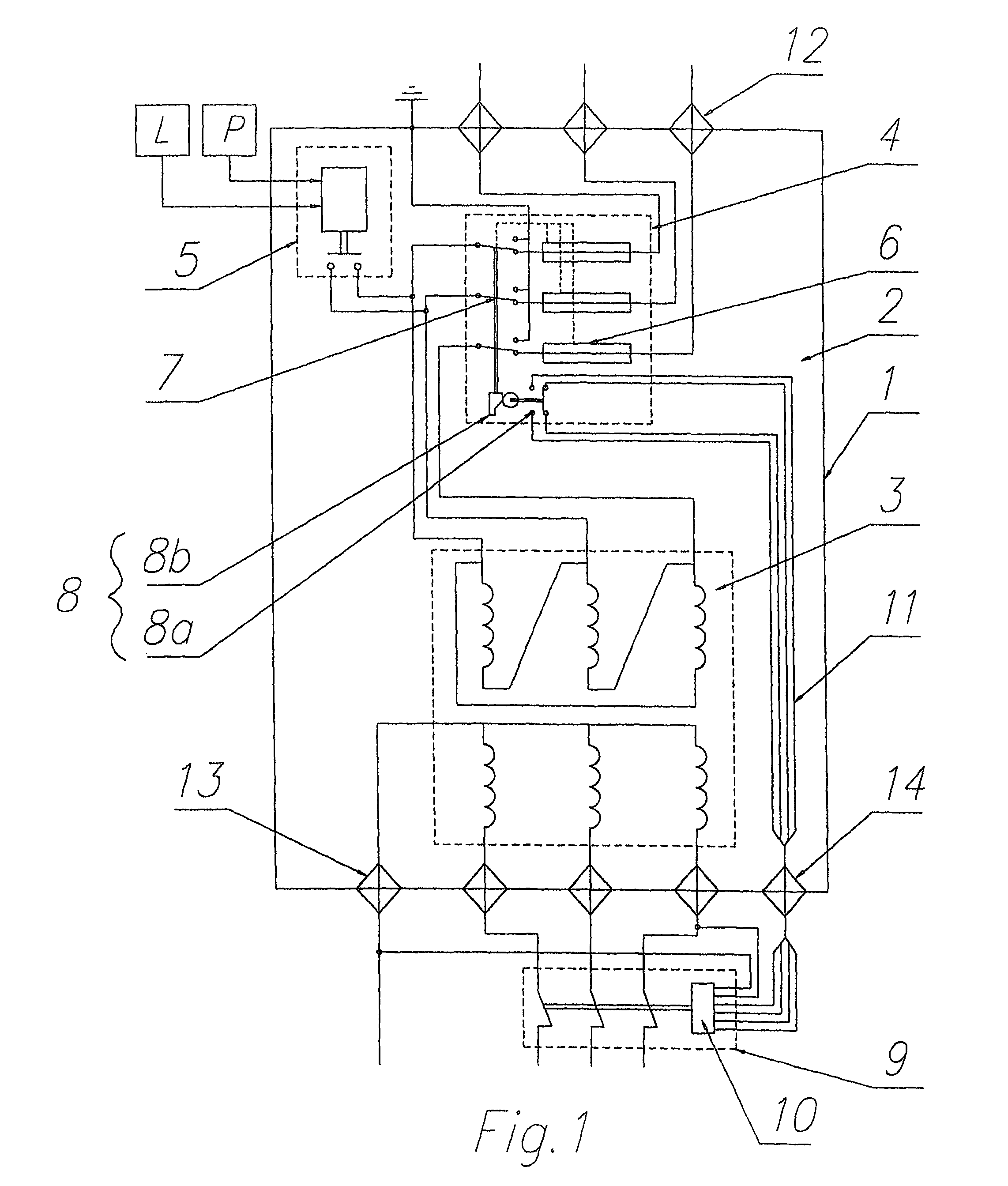
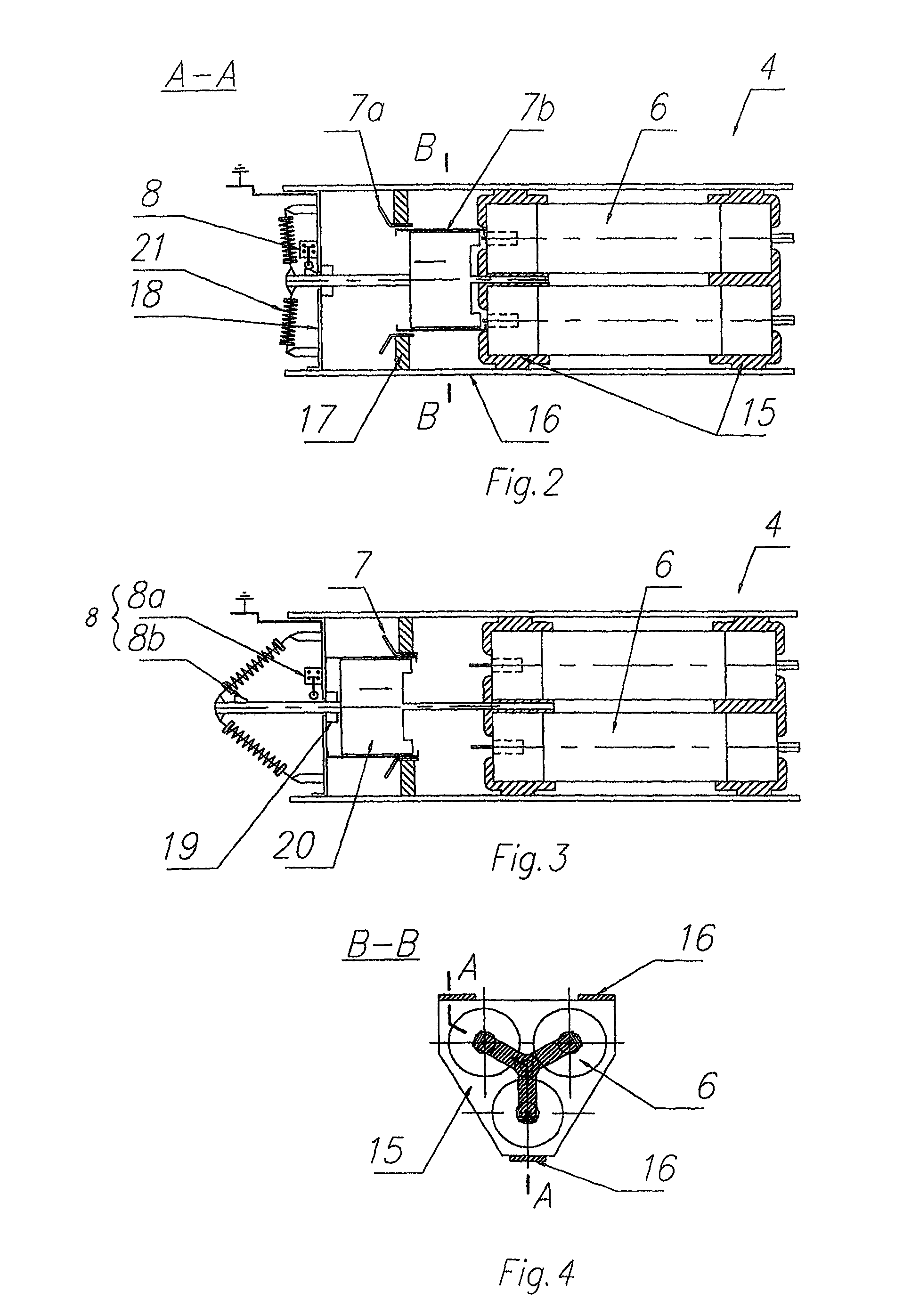
[0020]A distribution transformer has a closed tank 2 which houses an active part of the transformer 3, schematically shown in FIG. 1, comprising a magnetic core not shown in the drawing, primary windings of the transformer forming the primary circuit of the transformer, and secondary windings forming the secondary circuit of the transformer. The active part 3 is located in the tank 2 and immersed in transformer oil. Inside the tank 2 there is a disconnector 4 which is electrically coupled with the contacts of an oil level and pressure sensor 5, where the letter “L” denotes oil level, and the letter “P” denotes the pressure head. The disconnector 4 comprises at least two cylindrical current-limiting fuses 6 with tripping devices, and the drawing shows an embodiment with three fuses whose longitudinal axes are situated parallel to one another. Main contacts 7 of the disconnector are electrically connected with a primary winding of the active part 3 of the transformer 1. The disconnect...


PUM

PropertyMeasurementUnit
voltageaaaaaaaaaa
pressureaaaaaaaaaa
dimensionsaaaaaaaaaa

Abstract

A disconnector for distribution transformers with dielectric liquid intended for comprehensive protection of a power grid or for protecting distribution transformers. The disconnector provides at least two cylindrical current-limiting fuses located inside a transformer tank. Each fuse is electrically connected with an external phase power supply through fixed contacts and moving contacts of the disconnector with the active part of the transformer. The disconnector has an additional auxiliary contact which is electrically connected to a switch connected to the active part of the transformer on a low voltage side of the transformer.

Description

CROSS-REFERENCE TO RELATED APPLICATION[0001]This application claims priority of European patent application number 11460024 filed on May 6, 2011, and which is incorporated herein by reference.TECHNICAL FIELD[0002]The invention relates to a disconnector for distribution transformers with dielectric liquid intended for comprehensive protection of a power grid against the effects of failures caused by damage to the grid on the low voltage side or by damage to the transformer, and to an integrated system for protecting distribution transformers with dielectric liquid electrically connected with a switch at the low voltage side, or for distribution transformers operating in parallel in three-phase distribution grids.BACKGROUND ART[0003]Transformers filled with dielectric liquid and working in medium and / or high voltage grids incorporate protective systems whose function is to eliminate the effects of various failures and to disconnect power from the grid if there is an internal short cir...

Claims


Application Information

Patent Timeline
Patent Type & Authority Patents(United States)
IPC IPC(8): H02H7/04H01F27/40H01H71/12H01H85/02H01H85/20H01H85/30
CPCH01H71/122H01F2027/404H01H85/306H01H2085/0291H01H2085/2095
Inventor CIESIELSKI, SLAWOMIRKLYS, PAWELKLIMEK, MARCIN
Owner HITACHI ENERGY LTD
Why Eureka
Try Eureka