
Bulldozer

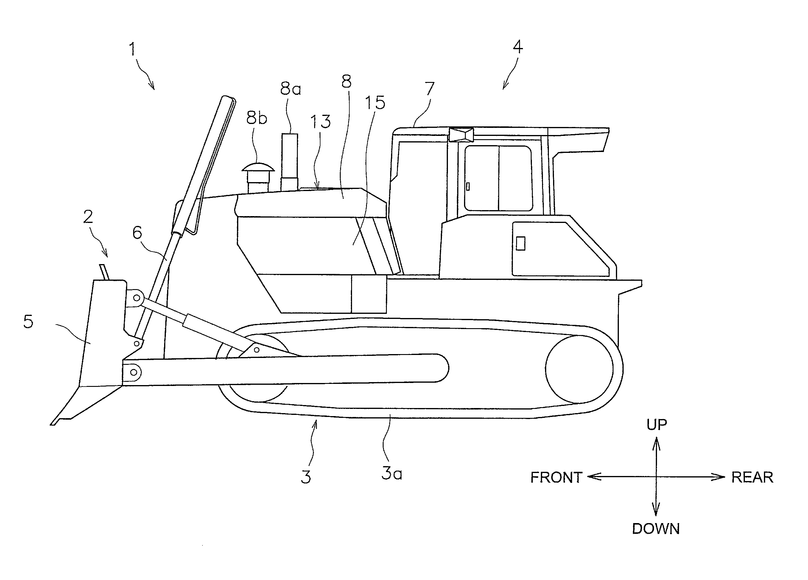
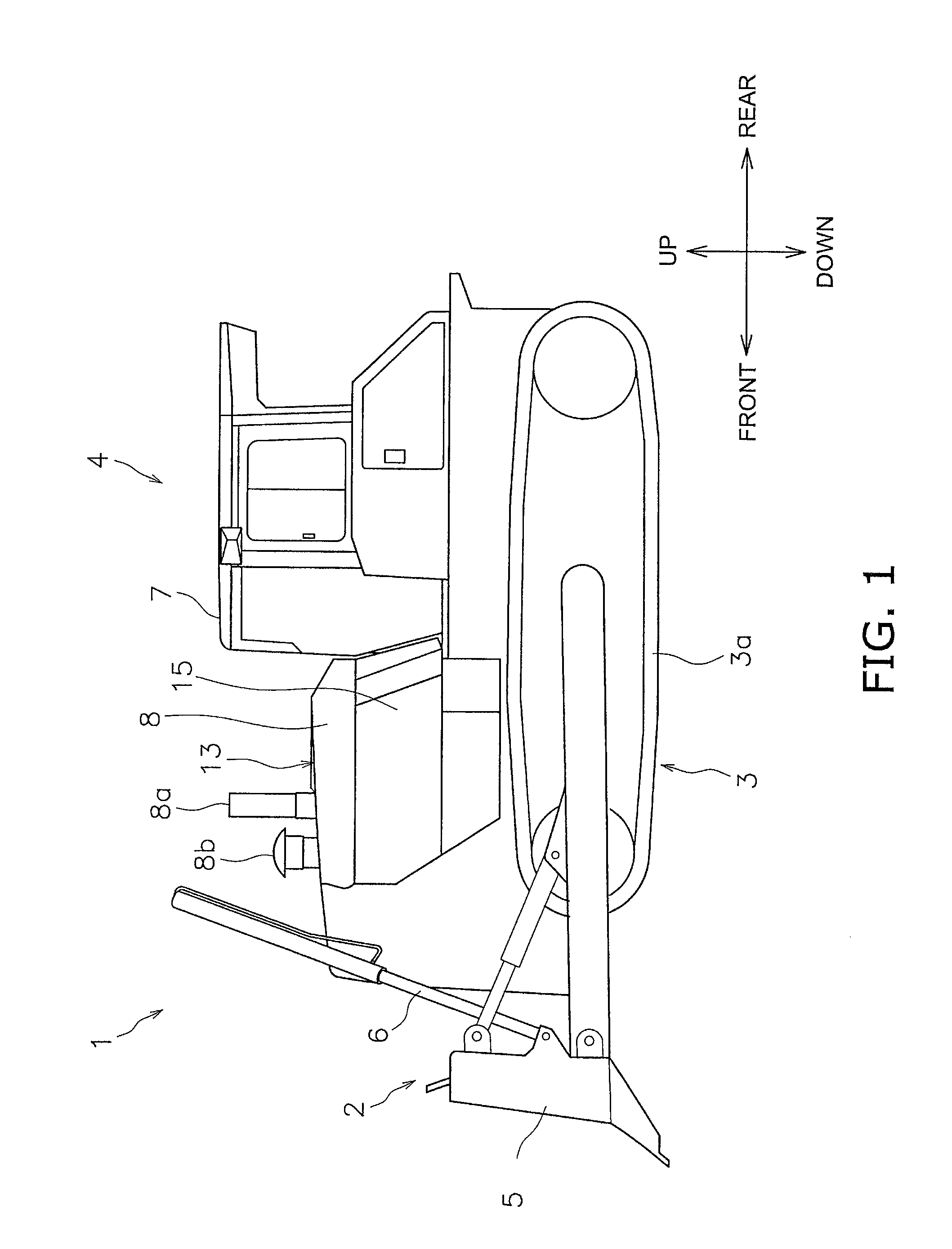
a bulldozer and engine technology, applied in the field of work vehicles, can solve problems such as reducing the operability of bulldozers, and achieve the effect of increasing the width of the engine compartment and maintaining the visibility of the operator

Active Publication Date: 2014-09-09
KOMATSU LTD
View PDF14 Cites 6 Cited by
  • Summary
  • Abstract
  • Description
  • Claims
  • Application Information

AI Technical Summary

Benefits of technology

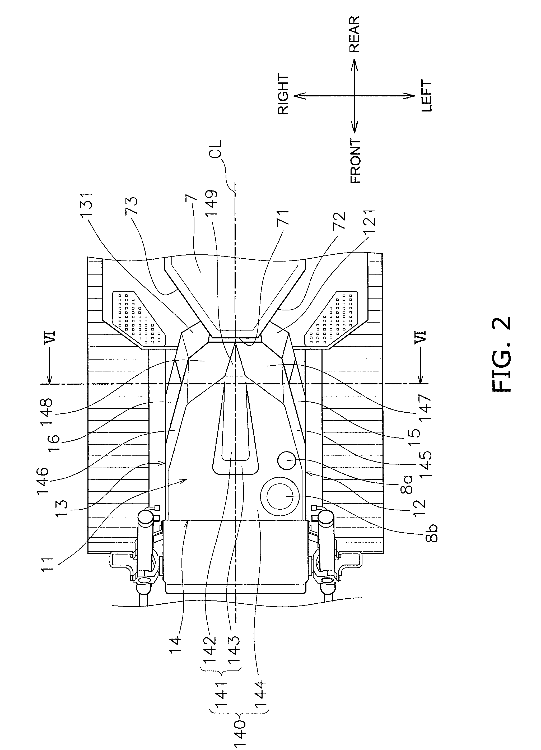
The present invention aims to provide a bulldozer with an engine compartment that has a narrower width, so that the operator's visibility is not compromised when exhaust treatment apparatuses are mounted. This results in a more compact engine compartment length without increasing its width, allowing for better visibility, particularly in the blade edge sections.

Problems solved by technology

As a result, the view of an operator is obstructed in the vicinity of both left and right edge sections of a front working implement (a blade), which results in reducing the operability of the bulldozer.

Method used


Image

  • Bulldozer
  • Bulldozer
  • Bulldozer

Examples


modified examples

[0094]An embodiment of the present invention is described above but the present invention is not limited thereto and various modifications are possible within the gist of the invention.

[0095]FIG. 5 illustrates an example where the second connection pipe 43 is not included in an inner space of the convex section 141, but a portion of the second connection pipe 43 may be included in the inner space of the convex section 141. If the second connection pipe 43 is arranged in this manner, it is easy to secure a gap between the second connection pipe 43 and the exhaust treatment apparatuses, which makes the assembling work easier.

[0096]In the present embodiment, the third inclined surface 149 is illustrated as a triangular shape, but the shape may be a rectangular shape such as a trapezoid. Even in this case, the window 74 of the cab 7 is arranged above the side which is the rear edge section of the third inclined surface (in other words, the side which is closest to the foremost surface 7...


PUM


Abstract

A bulldozer includes an engine, first and second exhaust treatment apparatuses arranged above the engine, a relay connection pipe connecting the first and second apparatuses, and an engine hood covering upper parts of the first and second apparatuses. The relay connection pipe has a cylindrical shaped main section, a first section connecting the main section and the first apparatus, and a second section connecting the main section and the second apparatus. The lower end of the main section is positioned above upper ends of the first and second apparatuses. The upper surface of the hood has a convex section protruding above the relay connection pipe and a base section formed integrally with the convex section below the convex section. At least a portion of a line segment extending along the upper edge of the main section overlaps an upper surface part of the convex section in a bulldozer top view.

Description

CROSS-REFERENCE TO RELATED APPLICATIONS[0001]This application is a U.S. National stage application of International Application No. PCT / JP2013 / 059555, filed on Mar. 29, 2013.BACKGROUND[0002]1. Field of the Invention[0003]The present invention relates to a work vehicle such as a bulldozer.[0004]2. Background Information[0005]In recent years, there has been demand for cleaning of exhaust in work vehicles such as bulldozers from the viewpoint of the natural environment protection (refer to US Patent Application Publication No. 2010 / 0186381 A1). As a result, an exhaust treatment apparatus which is more advanced than a conventional muffler is mounted in the work vehicle. For example, such an advanced exhaust treatment apparatus includes a diesel particulate filter (DPF) apparatus, a selective catalytic reduction (SCR) apparatus, or the like. The DPF apparatus reduces particulate matter in the exhaust. The SCR apparatus reduces nitrogen oxide (NOx) in the exhaust. The exhaust treatment ap...

Claims


Application Information

Patent Timeline
Patent Type & Authority Patents(United States)
IPC IPC(8): B60K11/00E02F3/76E02F9/08
CPCE02F9/0891E02F3/7609E02F9/0866F01N13/18F01N13/1805B60Y2200/411B60K13/04E02F3/7618F01N2340/04
Inventor NAKAGAMI, HIROSHIOZAKI, TAIRAOUNISHI, AKHITO
Owner KOMATSU LTD
Learn More