Electrical connector system

a technology of electrical connectors and connectors, applied in the direction of electrical devices, coupling device connections, transportation and packaging, etc., can solve the problems of hammering the disconnection of two connectors, and achieve the effect of lowering resistance and increasing curren

Active Publication Date: 2014-09-09
APTIV TECH LTD
View PDF12 Cites 93 Cited by
  • Summary
  • Abstract
  • Description
  • Claims
  • Application Information

AI Technical Summary

Benefits of technology

[0009]In a preferred embodiment, the CPA member further locks the correctly mated position of the first connector and the counter connector mechanically. Hereby, the CPA member can e.g. provide a secondary locking system by e.g. constraining the primary locking system which serves for the correct mating of the two connectors in the first place. In this way, the connectors cannot be unmated if the CPA member is in its locked position. Thereby, an additional safety system is provided which hampers the disconnection of the two connectors when the main power is turned on. To physically disconnect the two connectors, the CPA member inevitably has to be moved out of its locked position, thereby automatically turning of the main electrical power. Then the two connectors can safely be unmated. Preferably the electrical connector system comprises a switching device which is adapted to switch the signal circuit and the CPA member is adapted to interact physically with this switching device. If the signal circuit is e.g. realized in form of an electrical circuit, a switching device could e.g. be an electrical switch. The CPA member can e.g. interact physically with this switch, by pressing the switch when moved in the locked position. The switch then turns on or off the electrical circuit, which results in the turning on of the electrical power as described above. In a different embodiment, the switching device could be realized in form of two electrical contacts which close the signal circuit when they are in contact. This could be realized e.g. by two metallic wires which are bent in a U-shaped form, the curves of the U-shaped wires pressed against each other by a spring force, thereby establishing an electrical connection closing the signal circuit. In this case, the CPA member could be an electrically isolated tongue, being movable in between the two wires, thereby disconnecting the electrical connection and opening the signal circuit. A further embodiment exemplarily is given by the same members used inversely. In this case the two U-shaped wires are initially disconnected. When the CPA member is placed in its end position, it moves one or both of the wires, thereby pressing the two into electrical contact and closing the signal circuit. In a further embodiment the switching device is realized in form of a variable resistor. In this case, the CPA member is adapted to interact with the variable resistor changing the resistance of the signal circuit. In an exemplary case of a closed electrical circuit connected to a secondary power supply, this resistance change results in a change of electrical current. In this embodiment it is possible, e.g. by lowering the resistance to achieve a higher current activating a switching mechanism. In another embodiment, the signal circuit comprises two electrical contacts and the CPA member comprises a shorting clip to connect the two electrical contacts when inserted correctly into its end position. Thus, the signal circuit is initially open and closed by the CPA member.

Problems solved by technology

Thereby, an additional safety system is provided which hampers the disconnection of the two connectors when the main power is turned on.

Method used


Image

  • Electrical connector system
  • Electrical connector system
  • Electrical connector system

Examples


Embodiment Construction

[0014]In the following the invention is described exemplarily with reference to the enclosed figures in which:

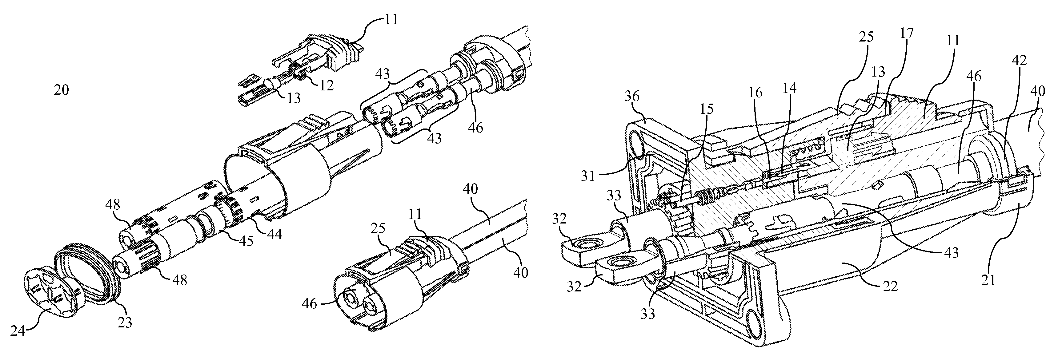
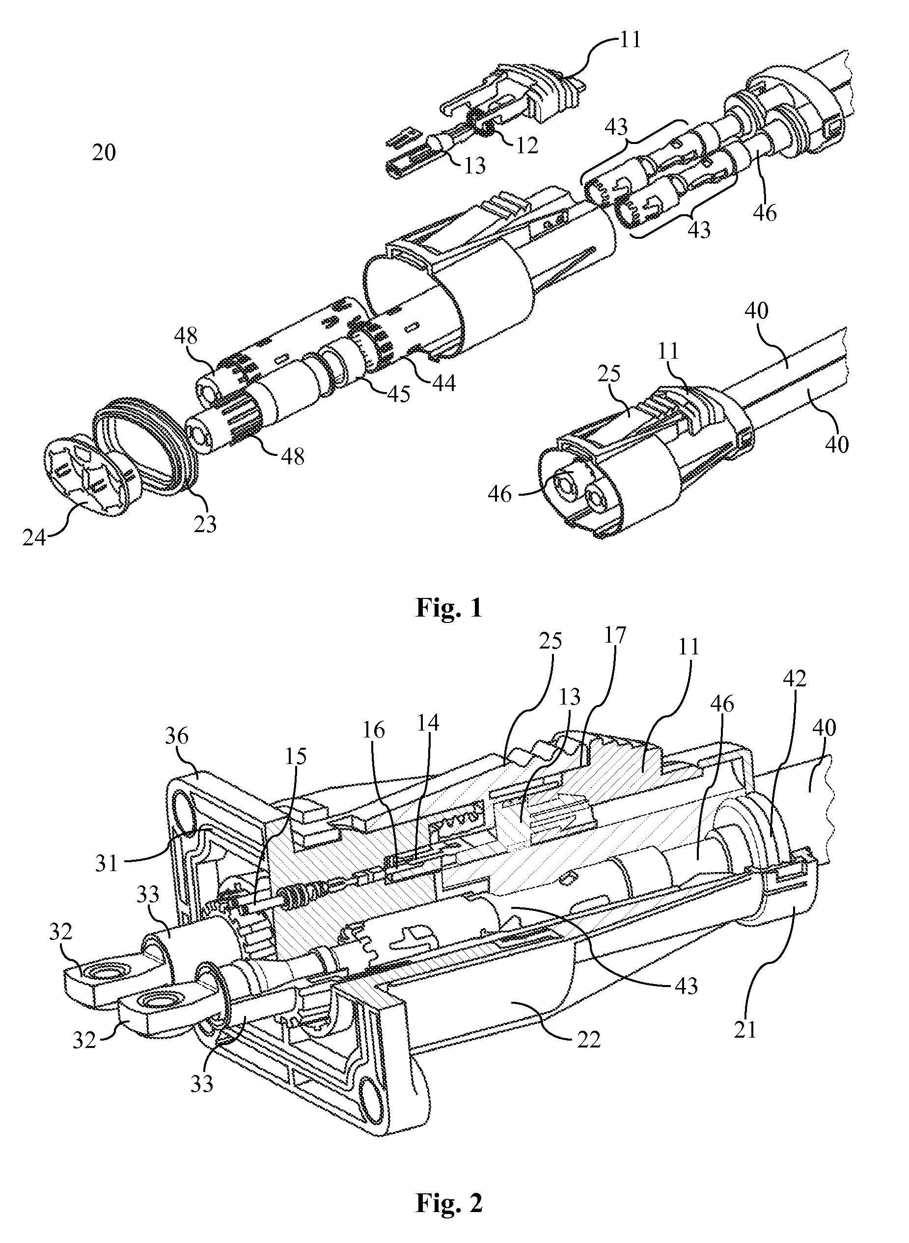
[0015]FIG. 1 is a schematic illustration of a connector system in accordance with the invention;

[0016]FIG. 2 is a perspective and partially cut view showing a preferred embodiment of a first connector 20 assembled with parts of a corresponding counter connector 30;

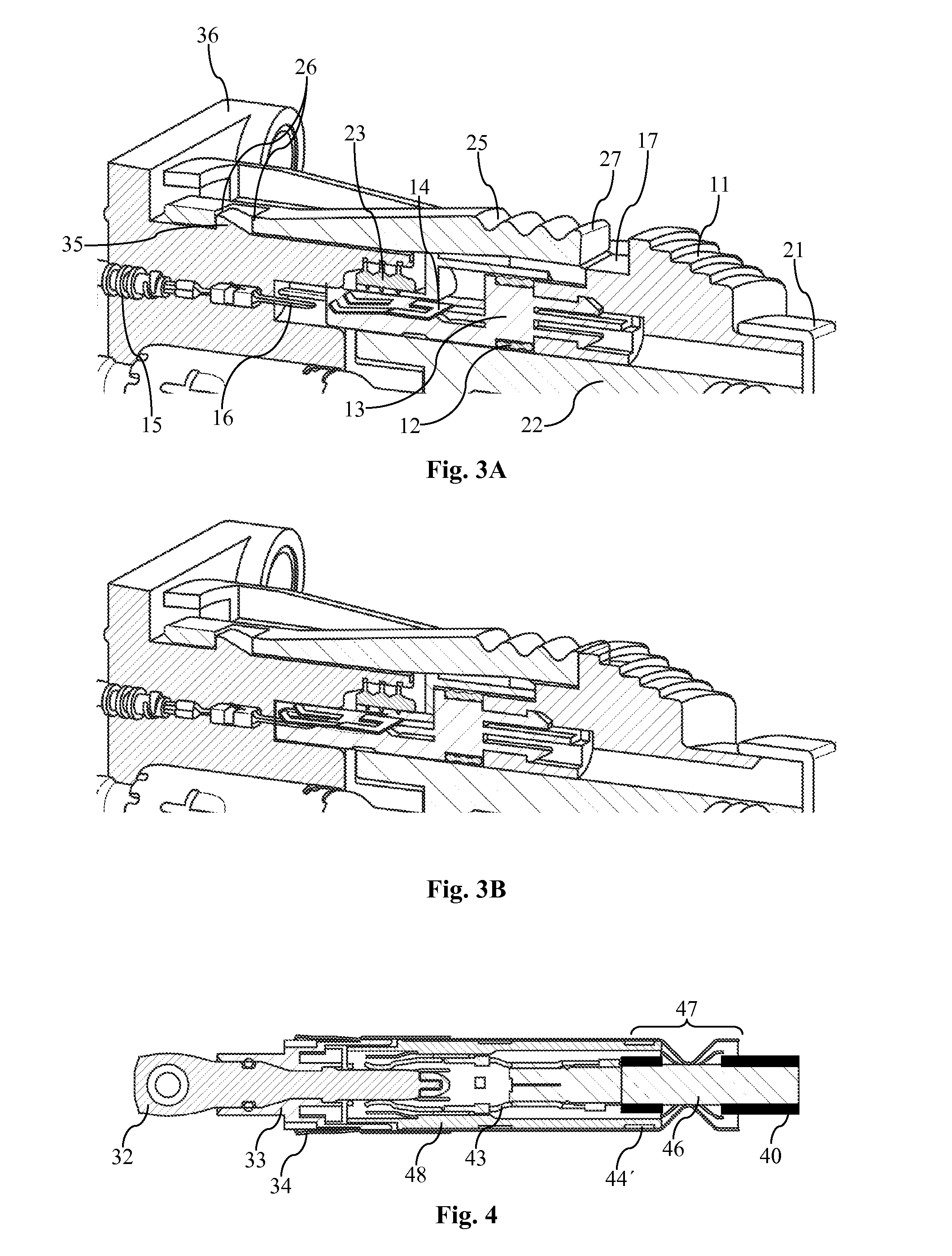
[0017]FIGS. 3A and 3B show details of the arrangement of FIG. 2;

[0018]FIG. 4 is a cross-sectional view showing a connection element of the electrical connector system;

[0019]FIG. 5 illustrates the assembly of a preferred embodiment of the corresponding counter connector 30; and

[0020]FIG. 6 is a schematic illustration of an exemplary signal circuit.

[0021]FIG. 1 is a schematic illustration showing an electrical connector system comprising a first connector 20 and a CPA member 10. In the figure, the upper illustration shows an exploded view and the lower illustration shows the parts in assembled condition. Exemplarily ...


PUM


Abstract

The present invention relates to an electrical connector system. The electrical connector system includes a first connector to be mated to a corresponding counter connector and it is further adapted to be connected to a signal circuit for activating an electrical power source upon switching. As a safety feature, the connector system further includes a connector position assurance (CPA) member assigned to the first connector, which is movable, whereby an end position is not reachable if the first connector is incorrectly mated to the counter connector. The CPA member is adapted to interact with the signal circuit if placed in said end position so that it activates of the electrical power source.

Description

1. FIELD OF THE INVENTION[0001]The present invention relates to electrical connector systems with additional features to improve the safety of the connection process, in particular with regard to electrical arcing.2. TECHNICAL BACKGROUND[0002]In high power applications it is often necessary to switch off the electrical power source before two connectors which connect the power lines are mated or unmated. Indeed, it is safer not to leave power terminals supplied by high power while the connectors are unmated and consequently while the terminals may be exposed. It is also useful to prevent possible arcing when the connectors are close to each other but not yet fully mated as it inevitably occurs during mating and unmating. Such arcing may be dangerous for persons connecting or disconnecting the power line and it may additionally damage the connectors. Further, a high voltage peak which may be induced by the arcing can damage electrical devices which are connected to the power system. ...

Claims


Application Information

Patent Timeline
Patent Type & Authority Patents(United States)
IPC IPC(8): H01R29/00B60L3/00B60L3/04B60L11/18H01R13/44H01R13/52H01R13/53H01R13/627H01R13/639H01R13/658H01R13/6593H01R13/70
CPCH01R13/70B60L3/04H01R13/658H01R13/701B60L3/0069B60L11/1818H01R13/6593Y02T90/121H01R13/639H01R13/5205B60L2270/34Y02T10/7005H01R13/5202Y02T10/7088Y02T90/14H01R13/53H01R13/6271B60L2270/32H01R13/44Y02T10/7072B60L53/16Y02T10/70Y02T90/12
Inventor GUNREBEN, MICHAELSCHWERIN, THOMASPABST, THOMAS BERNHARD
Owner APTIV TECH LTD
Why Eureka
Try Eureka