In-line strainer

a strainer and strainer technology, applied in the direction of vortex flow apparatus, filtration separation, separation process, etc., can solve the problems of decreased spraying force, decreased spraying amount, unsatisfactory spraying operation, etc., and achieves less frequent cleaning and easy removal of impurities

Active Publication Date: 2014-09-09
YAMAHO IND
View PDF5 Cites 12 Cited by
  • Summary
  • Abstract
  • Description
  • Claims
  • Application Information

AI Technical Summary

Benefits of technology

[0010]The present invention is invented in view of the above-described problems, and an object of the present invention is to provide an in-line strainer which includes a strainer element requiring less frequent cleaning, and which allows easy removal of impurities from the strainer element.
[0014]According to the in-line strainer of the present invention, the cyclone cylindrical body is disposed inside the housing, the strainer element is accommodated in the cyclone cylindrical body, and the strainer element is fitted to the housing between the outflow port of the housing and the cyclone outflow port. Accordingly, a part of impurities in a liquid can be captured in the cyclone cylindrical body, and the remaining impurities can be captured by the strainer element. Thus, filtration load on the whole of the strainer can be shared by the cyclone cylindrical body and the strainer element. As a result, the impurities to be captured by the strainer element are reduced, and the frequency of cleaning of the strainer element can be reduced.

Problems solved by technology

When the strainer element 83A or 83B is clogged during spraying operation, spraying force is decreased, and an amount of spraying is also decreased, resulting in unsatisfactory spraying operation.
However, impurities which are firmly stuck cannot be removed easily.
Particularly, in the case of the strainer element 83A, since the impurities are accumulated on an inner surface of the element, it is difficult to remove the impurities by using a brush.
On the other hand, when a mesh of the strainer element is coarse, impurities having a large diameter pass through the strainer element, which leads to a possibility that the nozzle at the downstream side is clogged with the impurities.

Method used


Image

  • In-line strainer
  • In-line strainer
  • In-line strainer

Examples


Embodiment Construction

[0031]An embodiment of the present invention will be described with reference to the drawings. It is noted that the embodiment described below is merely an example embodying the present invention, and should not be construed as limitation of the technical scope of the present invention.

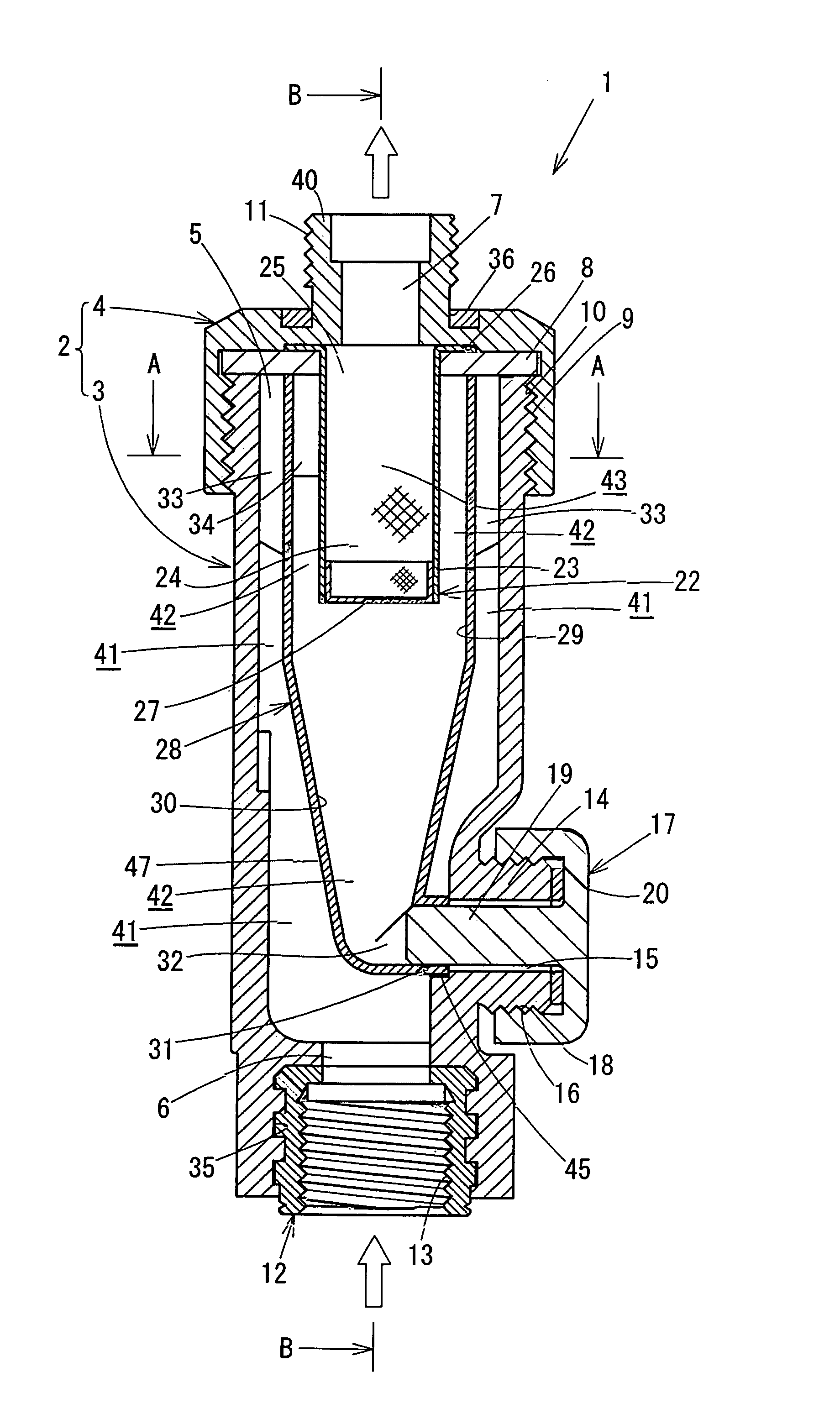
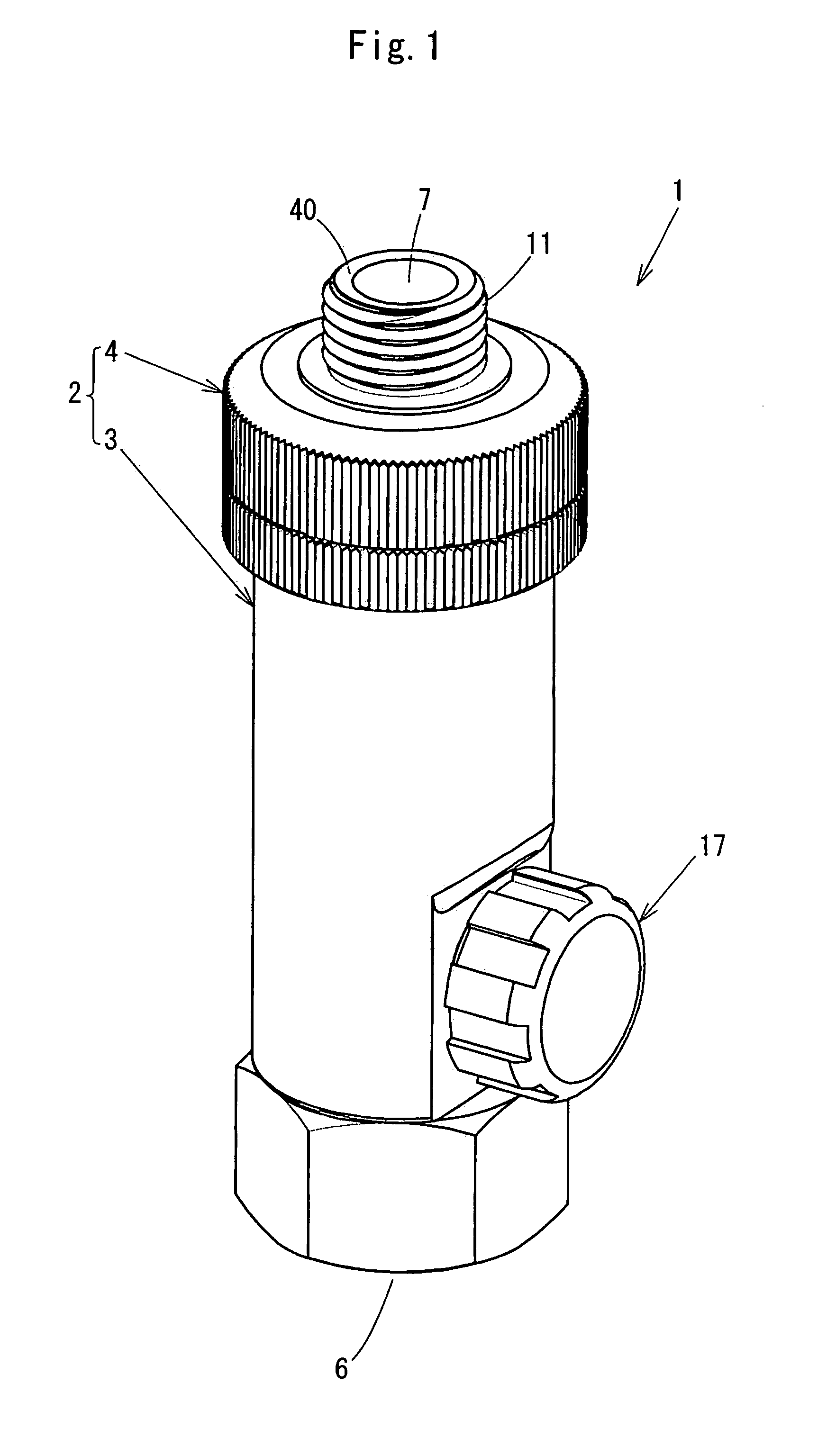
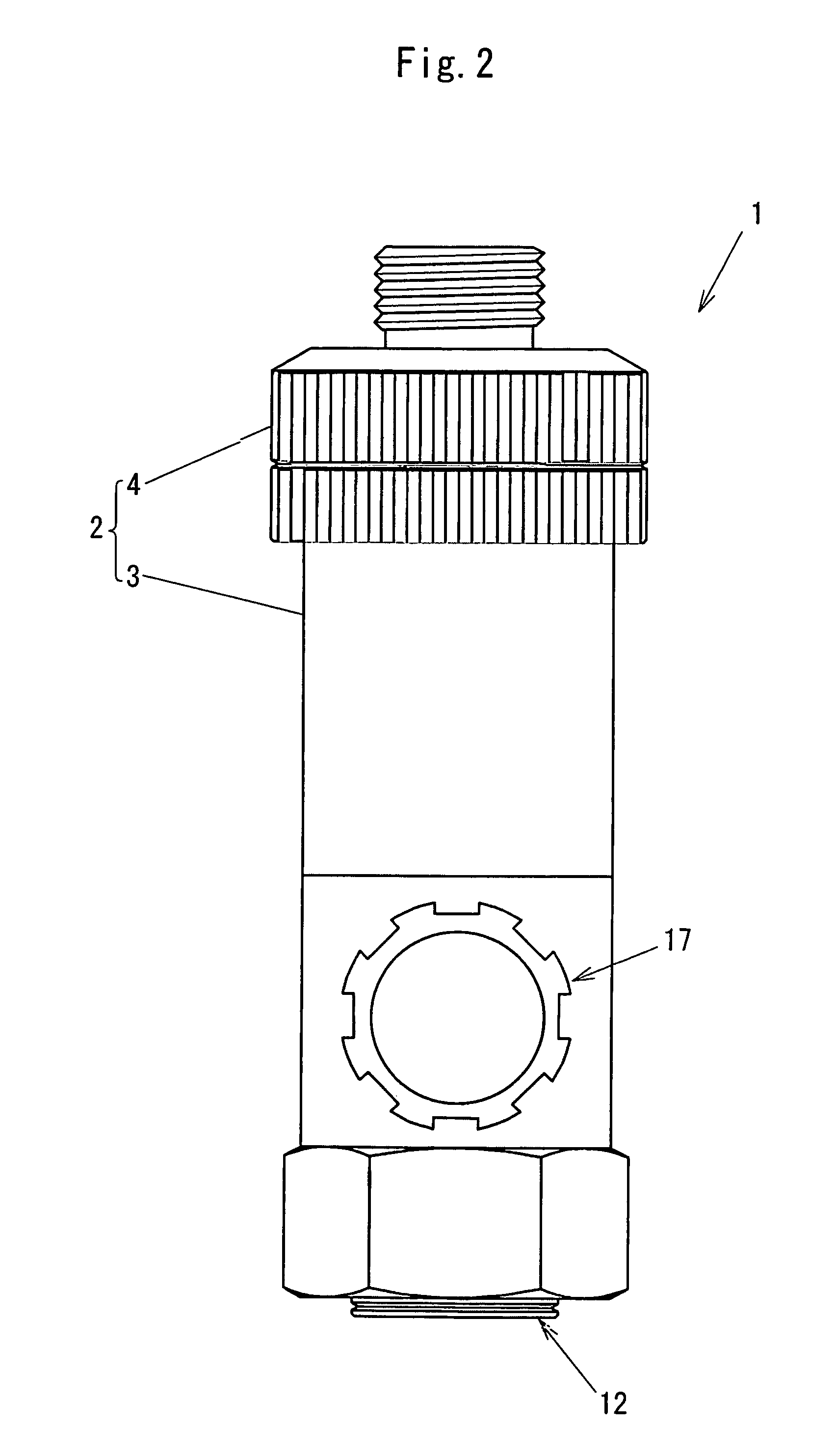
[0032]In FIG. 1 to FIG. 6, an in-line strainer 1 of the present embodiment includes a housing 2 which includes a cylindrical-shaped main body case 3 having an inflow port 6 arranged at its first cylinder end and having an opening portion 5 arranged at its second cylinder end, and a main body lid 4 fitted to the second cylinder end of the main body case 3 so as to seal the opening portion 5. Inside the housing 2, a strainer element 22 and a cyclone cylindrical body 28 are installed, which are described later in detail. The main body lid 4 is made of brass, for example, and the main body case 3 is formed of a transparent material such as polyethylene naphthalate. The polyethylene naphthalate is a synthe...


PUM

PropertyMeasurementUnit
inner diameteraaaaaaaaaa
shapeaaaaaaaaaa
spraying forceaaaaaaaaaa

Abstract

An in-line strainer 1 includes: a cylindrical-shaped housing 2 having an inflow port 6 for liquid and an outflow port 7 which are coaxial with each other; and a strainer element 22 disposed in the housing 2. A cyclone cylindrical body 28 having a diametrically-reduced cylinder portion 30 whose inner diameter is reduced toward one end, and having a cyclone inflow port formed on the other end, is arranged inside the housing 2 such that the diametrically-reduced cylinder portion 30 is close to the inflow port 6, and that the cyclone inflow port is close to the outflow port 7. A cylindrical-shaped strainer element 22 having a closed first end and an open second end is in the cyclone cylindrical body 28, and an open second end 25 of the strainer element 22 is connected to the outflow port 7 of the housing 2.

Description

BACKGROUND OF THE INVENTION[0001]1. Field of the Invention[0002]The present invention relates to an in-line strainer disposed in a pipe line for spraying a liquid such as an agricultural chemical solution and the like, so as to be coaxial with the pipe line.[0003]2. Description of the Background Art[0004]An example of conventional in-line strainers as described above is shown in FIG. 11A. An in-line strainer 61A shown in the diagram includes a housing 62 which includes a cylindrical-shaped main body case 63 having an inflow port 66 arranged at one end of the cylinder, and a main body lid 64 fitted to the other end of the cylinder of the main body case 63 in a sealed manner. Inside the housing 62, a valve seat 95 is formed in the vicinity of the inflow port 66, and a valve element 92 for opening or closing the valve seat 95 is installed. A cylindrical-shaped strainer element 83A is disposed between an inner circumference surface of the main body case 63 and the valve element 92 so as...

Claims


Application Information

Patent Timeline
Patent Type & Authority Patents(United States)
IPC IPC(8): B01D29/00B01D29/11B01D35/02
CPCB01D35/02B01D29/114B01D29/906B01D35/00B04C1/00
Inventor IMAGAWA, YOSHINARIYUKURA, NARUKI
Owner YAMAHO IND
Why Eureka
Try Eureka