Fuel cell system

a fuel cell and system technology, applied in the field of fuel cell systems, can solve the problems of reduced velocity at the ejector nozzle, system complexity, and insufficient recirculation of hydrogen-containing off-gas, and achieve the effects of compactness, stable power generation, and simplified system

Active Publication Date: 2014-09-09
NISSAN MOTOR CO LTD
View PDF12 Cites 2 Cited by
  • Summary
  • Abstract
  • Description
  • Claims
  • Application Information

AI Technical Summary

Benefits of technology

[0005]The present invention is intended to provide a fuel cell system that can recirculate the hydrogen-containing off-gas well regardless of changes in the flow rate of hydrogen-containing gas so that the system is simplified and made compact.
[0007]According to the present invention, irrespective of the increase and decrease in the flow rate of hydrogen-containing gas, the hydrogen-containing off-gas may be effectively recalculated and system is thus simplified to achieve compactness. In addition, when hydrogen-containing off-gas may not be circulated, by causing the anode pressure to increase and decrease intermittently, impurities within the solid polymer cell (water, nitrogen, etc.) are discharged. Thus, the hydrogen gas concentration across the upstream and downstream of the anode of solid polymer cell may be collectively improved accompanied by a more stable power generation.

Problems solved by technology

In the fuel cell system with a fuel recirculation type disclosed in Japanese Laid-Open Patent Application Publication No. 2003-151588, when the amount of supply of hydrogen gas is small, the velocity at the ejector nozzle is reduced, and due to the reduced Bernoulli effect, the hydrogen-containing off-gas is not sufficiently available for recirculation.
However, in the above described configuration, in addition to providing the fuel pump, control of the fuel pump must be carried out so that the system becomes complicated with the difficulty to achieve system compactness.

Method used


Image

  • Fuel cell system
  • Fuel cell system
  • Fuel cell system

Examples


Embodiment Construction

[0019]Descriptions of embodiments to carry out the present invention are now made below with reference to accompanied drawings.

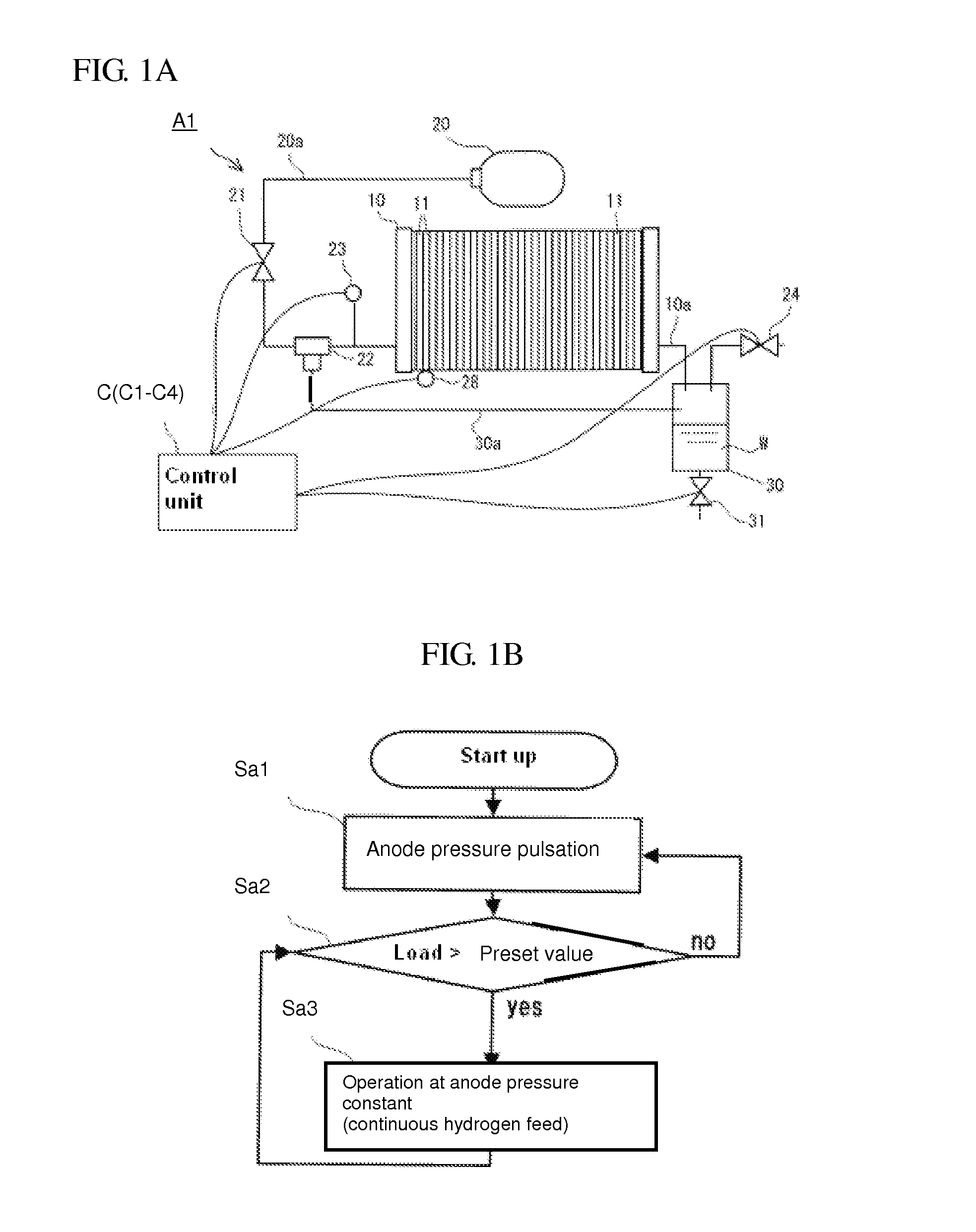
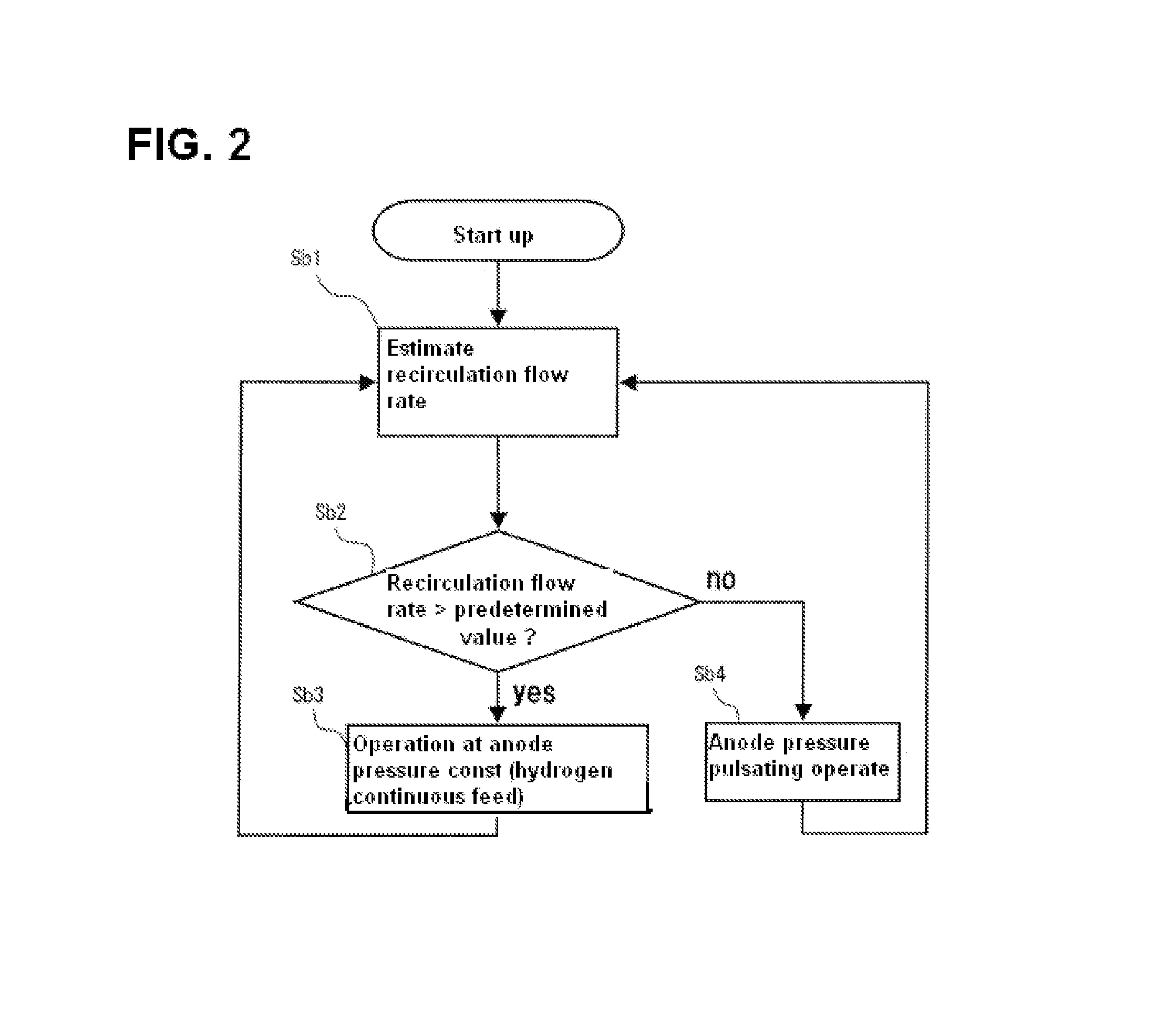
[0020]FIG. 1A is an explanatory diagram showing a schematic configuration of a fuel cell system A1 according to a first embodiment of the present invention, and FIG. 1B is a flowchart showing the operations of the fuel cell system A1 at the time of startup.

[0021]Note that, in FIGS. 1, 3, 5 and 6, among circulation systems of hydrogen-containing gas and oxygen-containing gas, only that for hydrogen-containing gas is illustrated and thus the diagram is somewhat simplified by omitting the illustration of the circulation system for oxygen-containing gas.

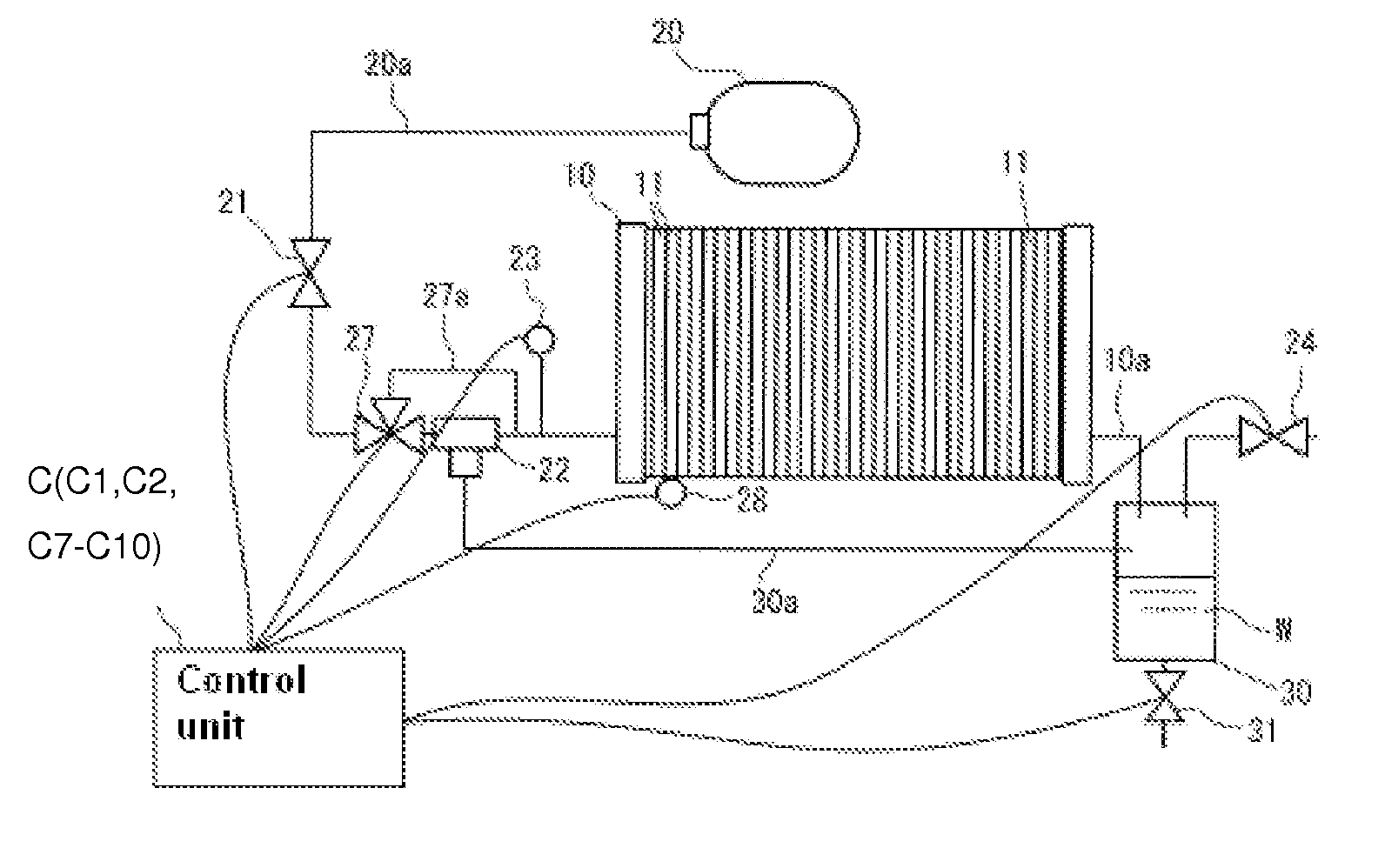
[0022]The fuel cell system A1 in the first embodiment according to the present invention is configured to include, in addition to cell stack 10, a fuel tank 20, a pressure regulating valve or modulator 21, an ejector 22, a pressure sensor 23, a temperature sensor 28, a nitrogen purge valve 24, a separate tank 30,...


PUM

PropertyMeasurementUnit
temperatureaaaaaaaaaa
flow rateaaaaaaaaaa
pressureaaaaaaaaaa

Abstract

The fuel cell system is simplified and made more compact while providing the favorable recirculation of hydrogen-containing off-gas regardless of the increase or decrease in its flow rate. The fuel cell system is provided with: a cell unit that generates electricity by means of separating hydrogen-containing gas and oxygen-containing gas from each other while placing in flow contact to each other; and a recirculation mechanism for recirculating to the cell unit hydrogen-containing off-gas discharged from the cell unit. The fuel cell system has a flow rate determination unit that determines whether or not the hydrogen-containing gas fed to the cell unit is less than a predetermined flow rate; and a gas feeding pressure varying mechanism that cause the pressure of the hydrogen-containing gas to vary to increase and decrease when it is determined that the hydrogen-containing gas fed to the cell unit is less than the predetermined flow quantity.

Description

TECHNICAL FIELD[0001]The present invention relates to a fuel cell system having a cell unit using a solid polymer type cell, for example.BACKGROUND[0002]The conventional fuel cell system of fuel recirculation type disclosed in the Japanese Laid-Open Patent Application Publication No. 2003-151588 is provided with a fuel cell to which a hydrogen gas as fuel and air as oxidant are respectively supplied for generating electricity, a fuel supply passage for supplying the above hydrogen gas to the fuel cell, a fuel recirculation passage for merging a hydrogen-containing off-gas as a unreacted fuel gas that has been discharged from the fuel cell at somewhere in the above fuel supply passage for re-circulating above hydrogen gas, a fuel pump for taking in the above hydrogen-containing off-gas to feed, and an ejector to inhale or taking in the above hydrogen-containing off-gas by making use of a negative pressure generated by the flow of the above hydrogen gas for merging with the hydrogen g...

Claims


Application Information

Patent Timeline
Patent Type & Authority Patents(United States)
IPC IPC(8): H01M8/06H01M8/04
CPCH01M8/04097H01M8/04753H01M8/04388Y02E60/50
Inventor IKEZOE, KEIGOICHIKAWA, YASUSHI
Owner NISSAN MOTOR CO LTD
Why Eureka
Try Eureka