

Radiation detection apparatus
a detection apparatus and radiation technology, applied in the direction of material analysis using wave/particle radiation, x/gamma/cosmic radiation measurement, instruments, etc., can solve the problems of difficult to measure a soft x-ray in the air or a solution, the latent demand for soft x-ray is very large, and the transmitting performance of soft x-ray is low
- Summary
- Abstract
- Description
- Claims
- Application Information
AI Technical Summary
Benefits of technology
Problems solved by technology
Method used
Image

Examples
Embodiment Construction
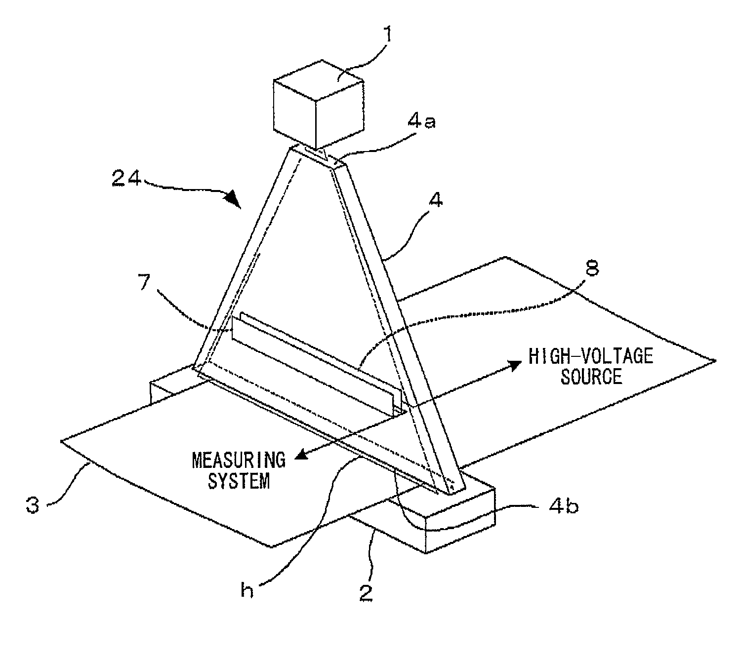
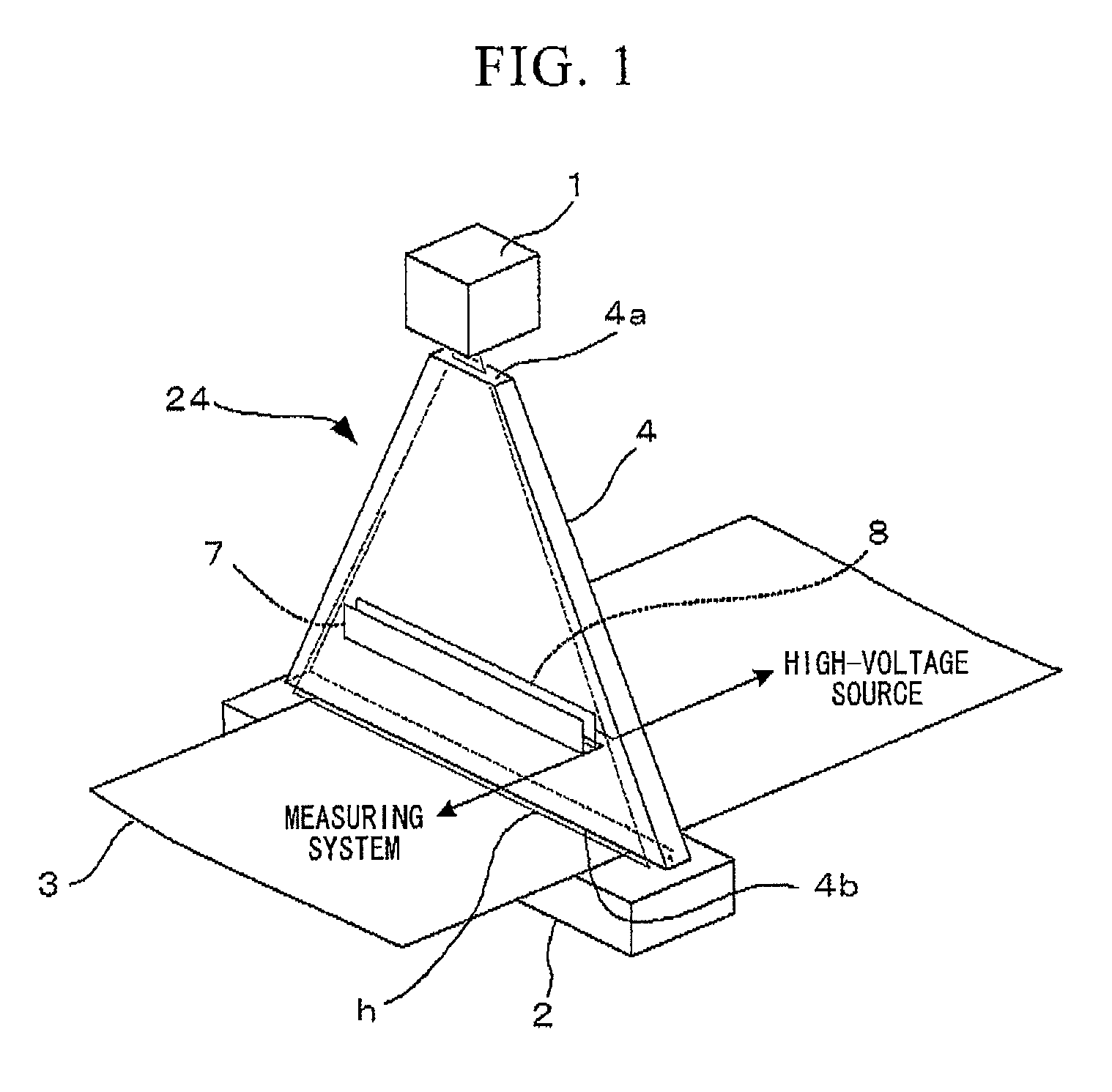
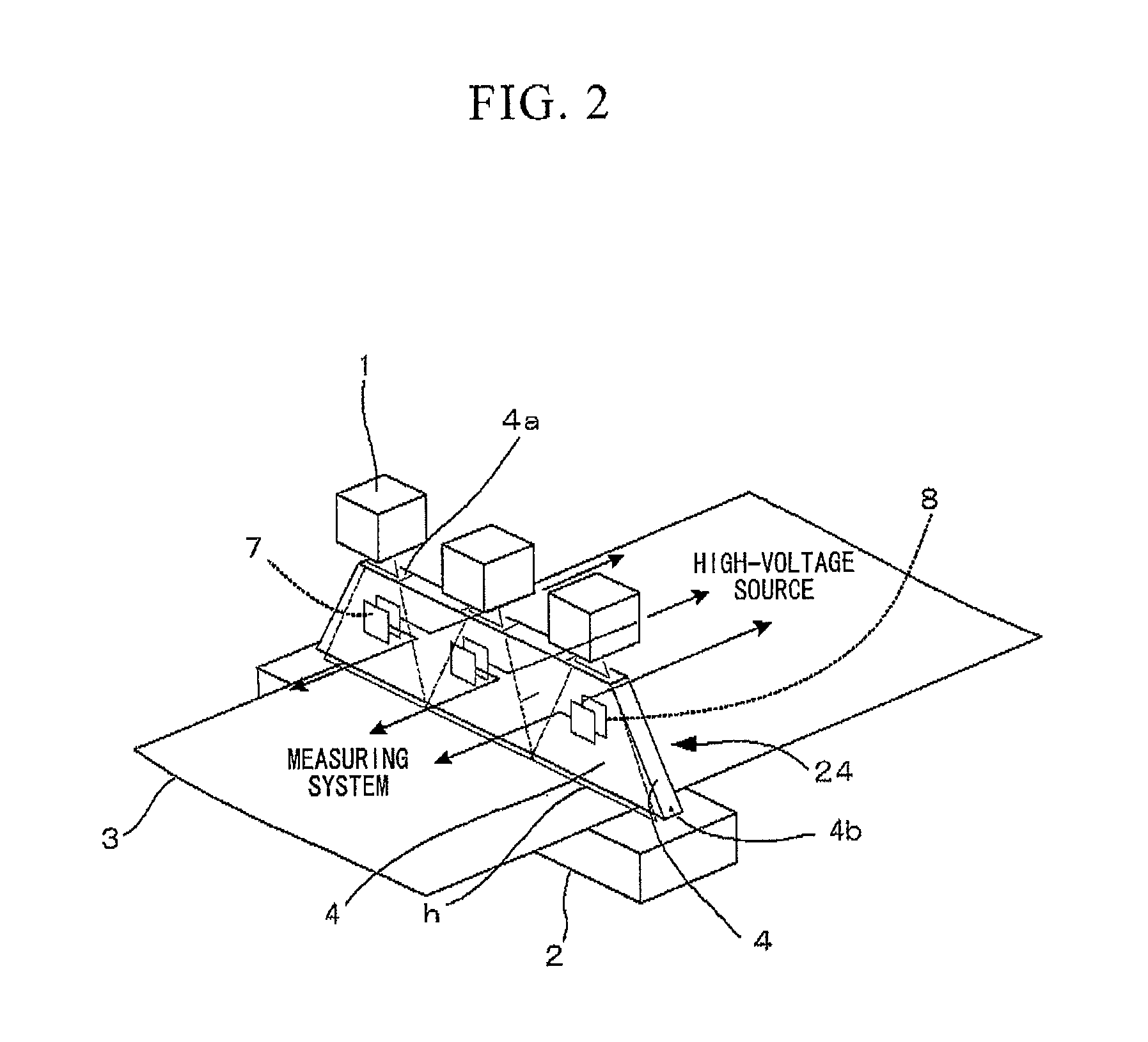
[0061]A radiation detection apparatus in accordance with the preferred embodiments of present invention does not generate beam hardening even though using radiation such as soft X-rays or β-rays, which are much absorbed by air. Further, the radiation detection apparatus in accordance with the preferred embodiments of present invention can detect radiation in a wide range even though the number of beam sources is small. The radiation detection apparatus in accordance with the preferred embodiments of present invention can measure the dose of radiation, which is irradiated from the beam source, in real time and stabilize the dose of radiation that is irradiated from the beam source. Since the radiation detection apparatus in accordance with the preferred embodiments of present invention can correct a measurement error caused by the variation of the dose of radiation, it may be possible to achieve highly accurate measurement. The radiation detection apparatus in accordance with the pre...
PUM
| Property | Measurement | Unit |
|---|---|---|
| pressure | aaaaa | aaaaa |
| energy | aaaaa | aaaaa |
| attenuation length | aaaaa | aaaaa |
Abstract
Description
Claims
Application Information