
Bullet-resistant transparent laminate composite and protection arrangement having a bullet-resistant transparent laminate composite

a transparent laminate, bullet-resistant technology, applied in the direction of transportation and packaging, other domestic articles, synthetic resin layered products, etc., can solve the problems of difficult installation, especially the strengthening of the frame structure, and achieve the effect of improving the bullet-resistant properties

Inactive Publication Date: 2014-09-16
IABG LICHTENAU +2
View PDF37 Cites 4 Cited by
  • Summary
  • Abstract
  • Description
  • Claims
  • Application Information

AI Technical Summary

Benefits of technology

The invention provides a transparent laminate composite with improved bullet-resistant properties for use in protection arrangements. The composite has a unique layered structure that elastically deforms when a shell or projectile penetrates, absorbing energy and reducing impact. The composite is designed in a conical configuration to provide a relatively large field of vision without being too large in size. The inner support structure of the holding device has a conical portion that provides ballistic protection on the inside of the composite. Overall, the invention provides a transparent composite with improved protection and reduced weight.

Problems solved by technology

By virtue of the glass panes included in those conventional composite glass blocks the overall weight is relatively high, which causes difficulty in terms of installation thereof and possibly requires especially strengthened frame structures in the vehicles and the like.

Method used


Image

  • Bullet-resistant transparent laminate composite and protection arrangement having a bullet-resistant transparent laminate composite
  • Bullet-resistant transparent laminate composite and protection arrangement having a bullet-resistant transparent laminate composite
  • Bullet-resistant transparent laminate composite and protection arrangement having a bullet-resistant transparent laminate composite

Examples


Embodiment Construction

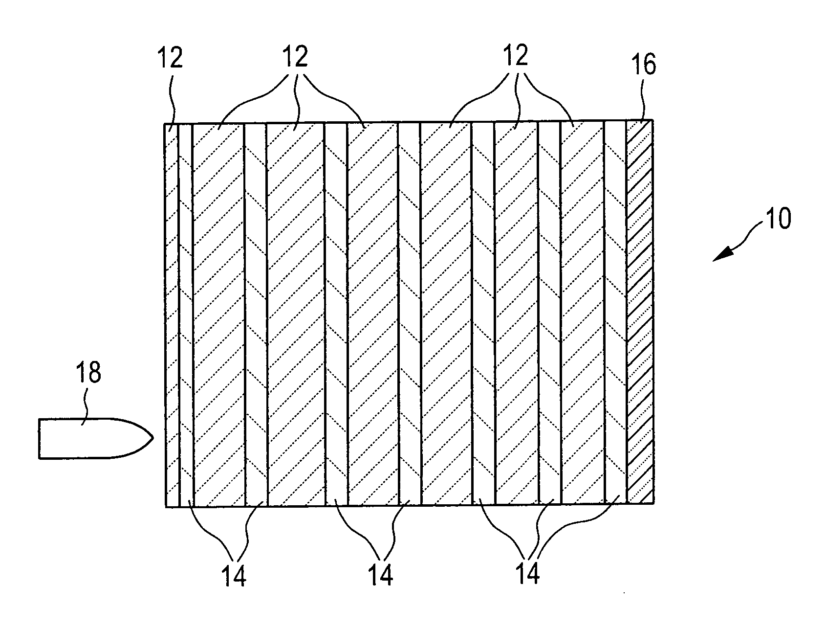
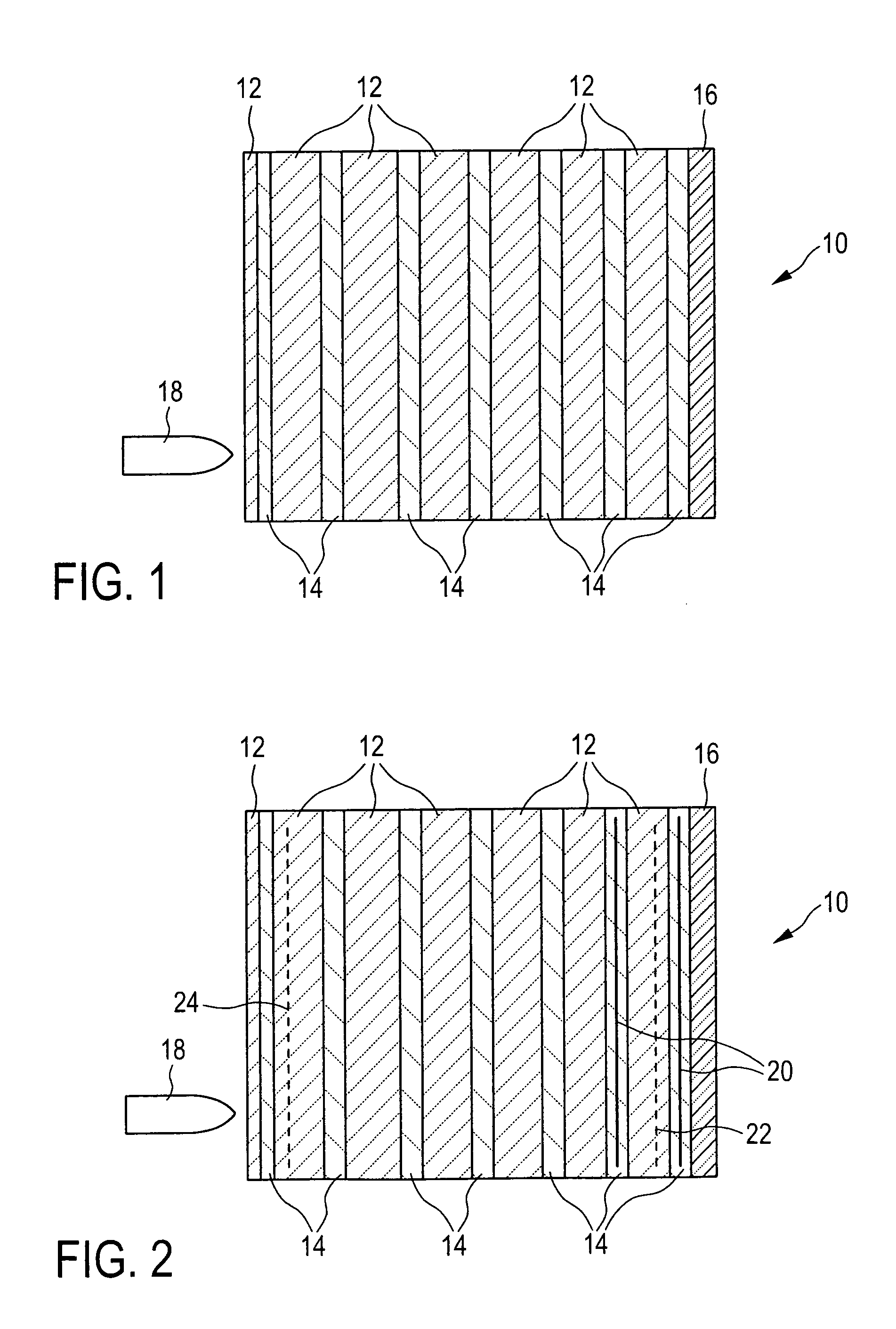
[0055]Referring to FIGS. 1 and 2 two preferred embodiments of a bullet-resistant transparent laminate composite (hereinafter also referred to as the composite body) according to the present invention are firstly described in greater detail.

[0056]The composite glass block 10 is made up of a plurality of plates 12 comprising a transparent first material such as for example acrylic glass (PMMA, Plexiglas), glass (silicate glass) or transparent ceramic, which are arranged at a mutual spacing one behind the other in the direction of the threat and between which there is a respective intermediate layer 14 comprising a transparent second material such as for example polyurethane (PU) or thermoplastic polyurethane (tPU). Arranged on the side of the composite body 10, that is remote from the threat—optionally by way of the connection of a further intermediate layer 14 comprising the transparent second material—there is also preferably a plate 16 of polycarbonate (PC) which in known fashion p...


PUM

PropertyMeasurementUnit
thicknessaaaaaaaaaa
thicknessaaaaaaaaaa
thicknessaaaaaaaaaa

Abstract

A bullet-resistant transparent laminate composite (10) has at least two plates (12) arranged one behind the other and at a spacing relative to each other in the direction of threat and comprising a transparent first material with a modulus of elasticity of at least about 1,500 N / mm2, and a respective intermediate layer (14) of a transparent second material with a lower modulus of elasticity than that of the first material between two adjacent plates (12). The layer thicknesses of the plates (12) and the intermediate layer or layers (14) are so selected that the overall layer structure of the layer composite (10) of plates and intermediate layer or layers has a modulus of elasticity which is at least about 10% lower in comparison with a block made exclusively from the first material and of the same overall thickness.

Description

CROSS-REFERENCE TO RELATED APPLICATIONS[0001]The present application claims priority under 35 U.S.C. §120 to International Patent Application PCT / EP2009 / 004255, filed Jun. 12, 2009, entitled “BULLET-RESISTANT TRANSPARENT LAMINATE COMPOSITE AND PROTECTION ARRANGEMENT HAVING A BULLET-RESISTANT TRANSPARENT LAMINATE COMPOSITE,” and international priority under 35 U.S.C. §119 to co-pending German Application DE 10 2008 028 318.5, filed Jun. 13, 2008, entitled “DURCHSCHUSSHEMMENDER TRANSPARENTER SCHICHTVERBUND UND SCHUTZANORDNUNG MIT EINEM DURCHSCHUSSHEMMENDEN TRANSPARENTEN SCHICHTVERBUND” and hereby incorporates the entire contents and disclosures of these applications herein by reference in their entirety.BACKGROUND OF THE INVENTION[0002]1. Field of the Invention[0003]The present invention concerns a bullet-resistant transparent laminate composite, a process for the production thereof and a protection arrangement having a bullet-resistant transparent laminate composite.[0004]2. Technica...

Claims


Application Information

Patent Timeline
Patent Type & Authority Patents(United States)
IPC IPC(8): F41H5/04B32B7/022B32B7/027B32B7/12B32B17/10B32B27/08B32B27/30F41H5/26
CPCB32B7/12F41H5/263F41H5/0407B32B27/08B32B17/10844B32B27/30B32B2369/00B32B7/02B32B9/005B32B9/045B32B27/304B32B27/36B32B27/365B32B27/40B32B2270/00B32B2307/412B32B2307/54B32B2571/02B32B2605/00B32B2605/16B32B2605/18B32B17/10064B32B17/1077B32B7/022B32B7/027
Inventor KRUGER, THOMASHINRICHSEN, DENNIHAMPEL, JANSCHAFER, ROGER
Owner IABG LICHTENAU
Learn More