Sealing frame and method for covering a component

a technology of sealing frame and component, applied in the direction of non-metallic protective coating application, electrical apparatus casing/cabinet/drawer, semiconductor/solid-state device details, etc., can solve the problem of increasing the construction space that is needed, and the gap between the molding compound and the thermoplastic synthetic material

Inactive Publication Date: 2014-09-16
ROBERT BOSCH GMBH
View PDF21 Cites 0 Cited by
  • Summary
  • Abstract
  • Description
  • Claims
  • Application Information

AI Technical Summary

Benefits of technology

[0009]Because of the design of the sealing frame having an upper frame part and a lower frame part, which may be detachably joined together, it is possible for the frame to be re-used for similar parts, in particular in mass production of components. Because it is possible to remove the frame again after the component has been covered with the molding compound, the frame does not increase the construction space that is needed for the component. In addition, use of the frame makes it possible to achieve a burr-free covering of the component.
[0031]After the molding material has cured, the module is removed from the casting mold. During cooling, the sealing frame and the casting material contract, as described earlier. This causes a gap to form between molding material and sealing frame. The frame may be removed in a simple manner by detaching the connection, and re-used for another module.

Problems solved by technology

Because it is possible to remove the frame again after the component has been covered with the molding compound, the frame does not increase the construction space that is needed for the component.
This causes a gap to form between the molding compound and the thermoplastic synthetic material, which has not bonded with the molding compound.

Method used


Image

  • Sealing frame and method for covering a component
  • Sealing frame and method for covering a component
  • Sealing frame and method for covering a component

Examples


Embodiment Construction

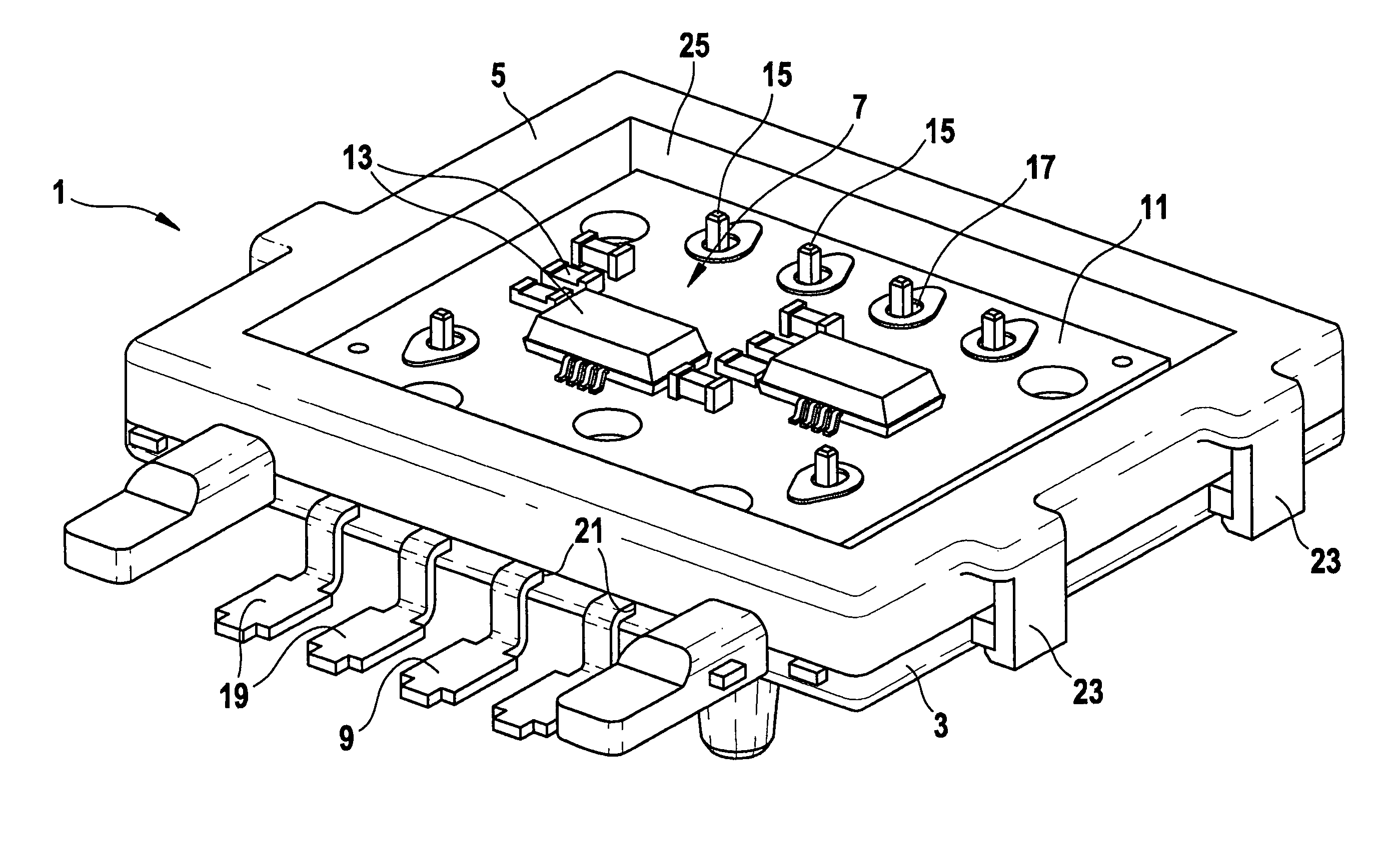
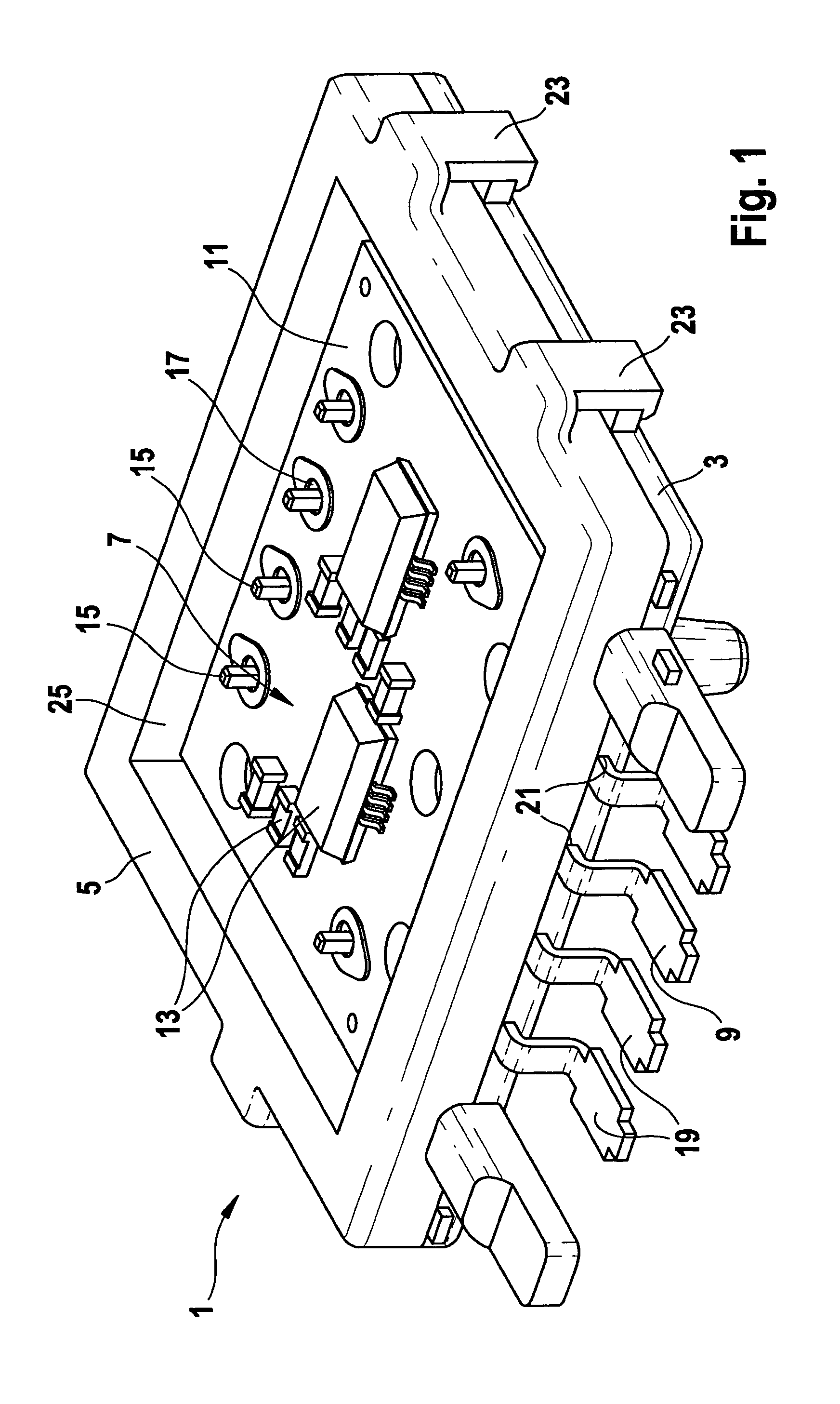
[0034]FIG. 1 shows a schematic depiction of a sealing frame with punched grid and circuit board clipped in place.

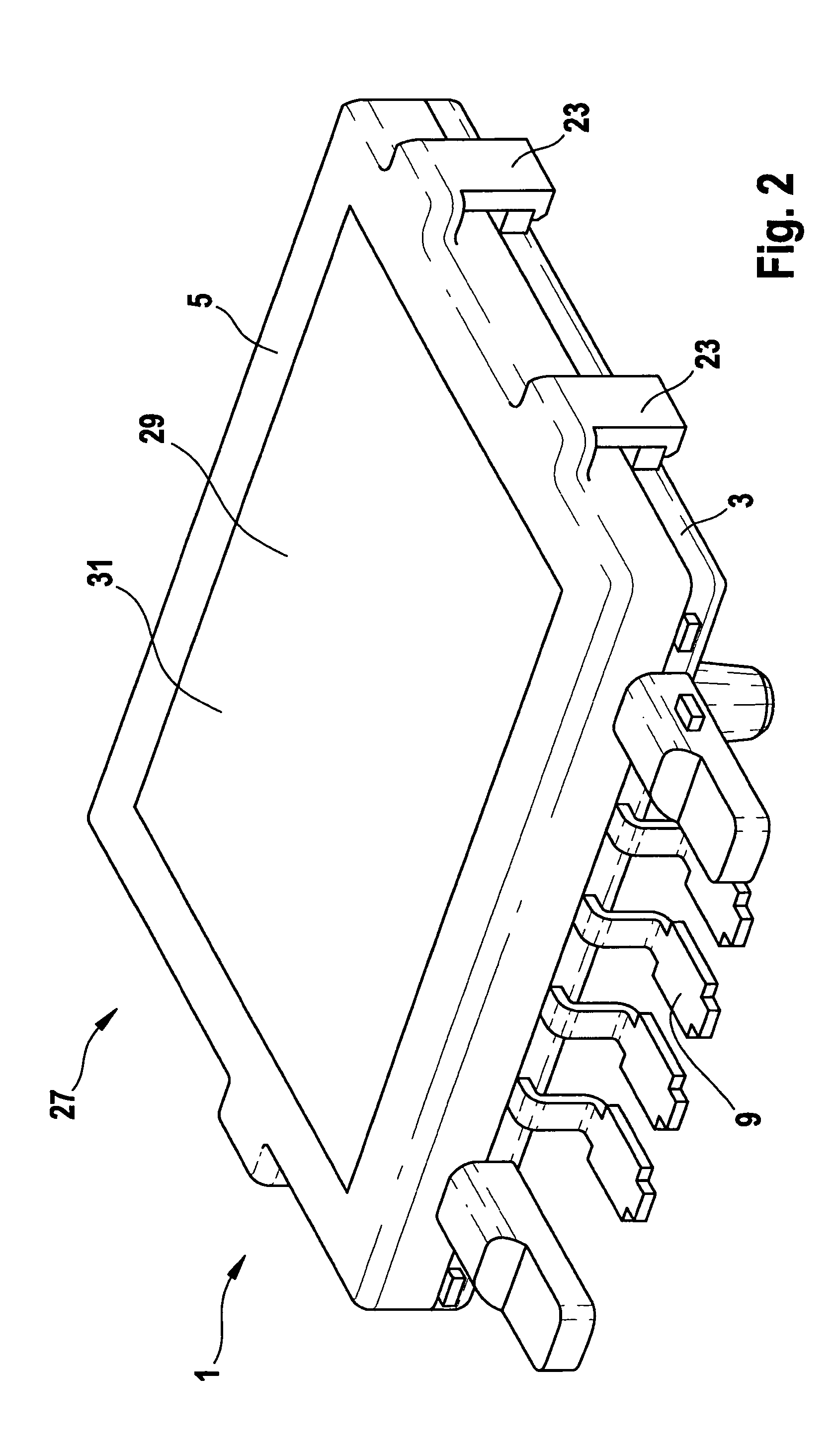
[0035]A sealing frame 1 designed according to the present invention includes a lower frame part 3 and an upper frame part 5. Lower frame part 3 and upper frame part 5 are joined together to make sealing frame 1.

[0036]Lower frame part 3 and upper frame part 5 are preferably made of a thermoplastic synthetic material. Because a thermoplastic synthetic material is used, lower frame part 3 and upper frame part 5 may be manufactured in a simple manner using a spray molding process. The thermoplastic synthetic material of which lower frame part 3 and upper frame part 5 are made is preferably a plastic, since it does not bond with the material of the molding compound. Suitable thermoplastic synthetic materials are for example perfluoroalkoxy copolymers.

[0037]Sealing frame 1 surrounds a component 7. In the specific embodiment depicted here, component 7 is a circuit board 11 conne...


PUM

PropertyMeasurementUnit
temperatureaaaaaaaaaa
perimeteraaaaaaaaaa

Abstract

A sealing frame for delimiting a surface of a component which is to be covered with a molding compound includes an upper frame part and a lower frame part which may be detachably joined together. The component to be covered with the molding compound is enclosable by the upper frame part and the lower frame part in such a way that a cavity is formed by the sealing frame and the component. The component is inserted into the upper frame par and lower frame part, and the upper and lower frame part are joined to form the sealing frame, so that the cavity is formed which is enclosed by the component and the upper frame part, and a molding compound is introduced into the cavity and cured to form a cover.

Description

BACKGROUND OF THE INVENTION[0001]1. Field of the Invention[0002]The present invention relates to a sealing frame and a method for delimiting a surface of a component which is to be covered with a molding compound.[0003]2. Description of Related Art[0004]To protect components from external environmental influences or influences of media, it is customary to cover the component with a molding compound. As the molding compound, it is usual here to employ epoxy low-pressure molding materials, which are applied to a surface of the component that is to be protected.[0005]In particular in the case of electrical components, for example of electronic functional elements such as semiconductor elements and chips, increasingly higher demands are being made in regard to their temperature resistance, media resistance, performance improvement and reliability, in particular in safety-relevant applications. As a result of covering them with the molding compound, media from the environment are not abl...

Claims


Application Information

Patent Timeline
Patent Type & Authority Patents(United States)
IPC IPC(8): H05K5/00H05K3/28H05K5/06
CPCH05K3/284H05K5/065H05K2203/1469H05K2203/1316H01L23/02H01L23/28H05K3/28H05K5/06
Inventor GEISE, STEPHAN
Owner ROBERT BOSCH GMBH
Why Eureka
Try Eureka