Rotary tool, in particular a drill

a rotary tool and drill bit technology, applied in the field of rotary tools, can solve the problems of increasing undesirable burrs at the exit of drill holes, high mechanical and thermal loading of cutting corners in rotary tools, etc., and achieves the effects of reducing the load on cutting corners, simple geometry, and increasing service li

Active Publication Date: 2014-09-16
KENNAMETAL INC
View PDF44 Cites 14 Cited by
  • Summary
  • Abstract
  • Description
  • Claims
  • Application Information

AI Technical Summary

Benefits of technology

[0010]The decisive advantage of this configuration can be seen in the fact that the corner bevels are assigned different functions due to the different configuration thereof. Thus, the roughing bevel serves for initial or rough machining and the finishing bevel serves for re-work or finish machining. Due to this measure, a burr is largely avoided at through-holes on account of the finishing bevel. At the same time, the configuration of the roughing bevel ensures that the loading of the cutting corners is reduced and the service life is thereby increased overall.
[0011]The use of additional secondary cutting edges can be dispensed with and is therefore preferably dispensed with, thereby resulting overall in a rotary tool of simple geometry which is simpl

Problems solved by technology

During the cutting operation, for example using drills, but also by means of reamers, milling cutters, in particular end mills, step drills, deep-hole drills or “three-lipped cutters”, there is generally the problem that the cutting corner is subjected t

Method used


Image

  • Rotary tool, in particular a drill
  • Rotary tool, in particular a drill
  • Rotary tool, in particular a drill

Examples


Embodiment Construction

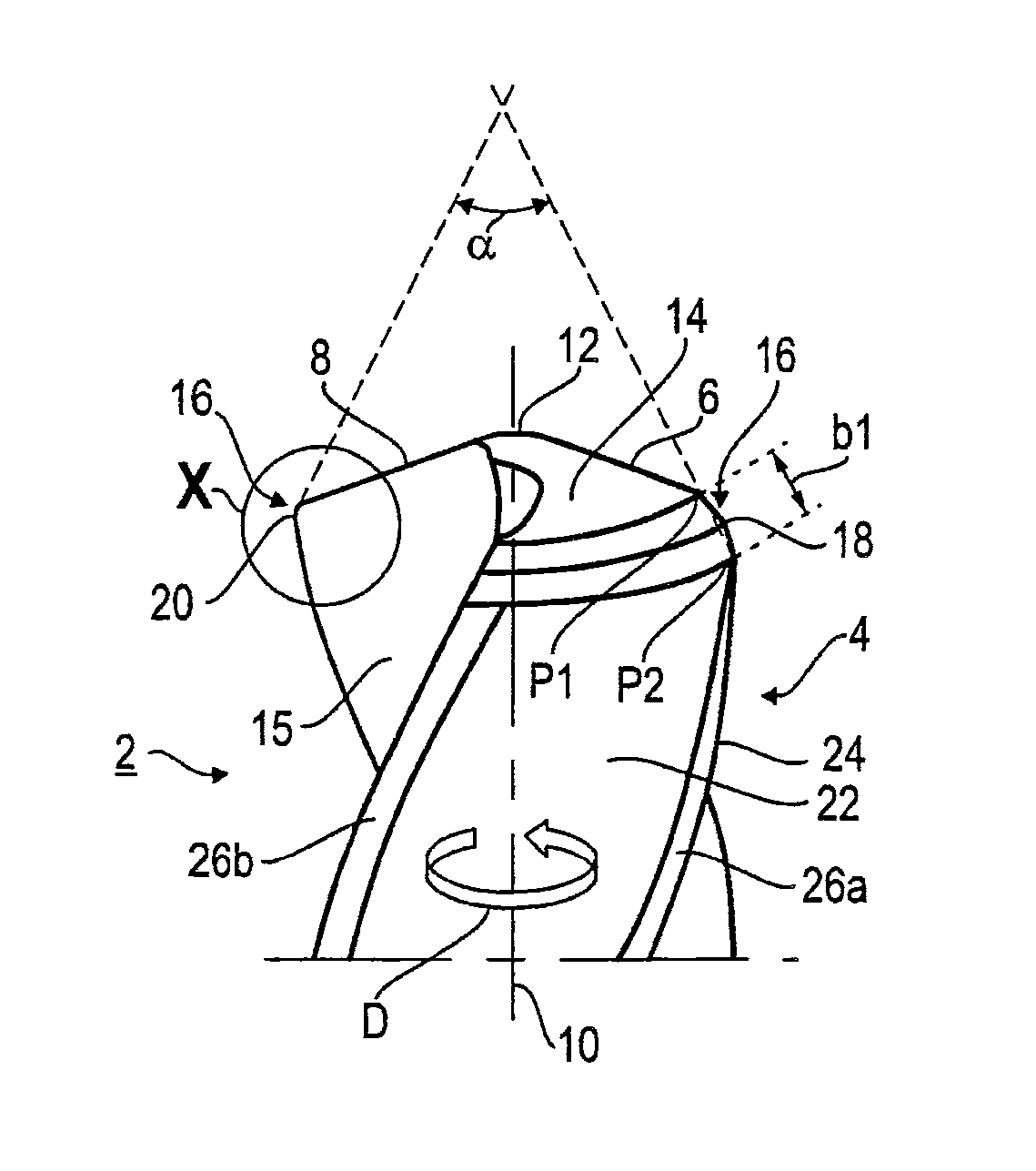
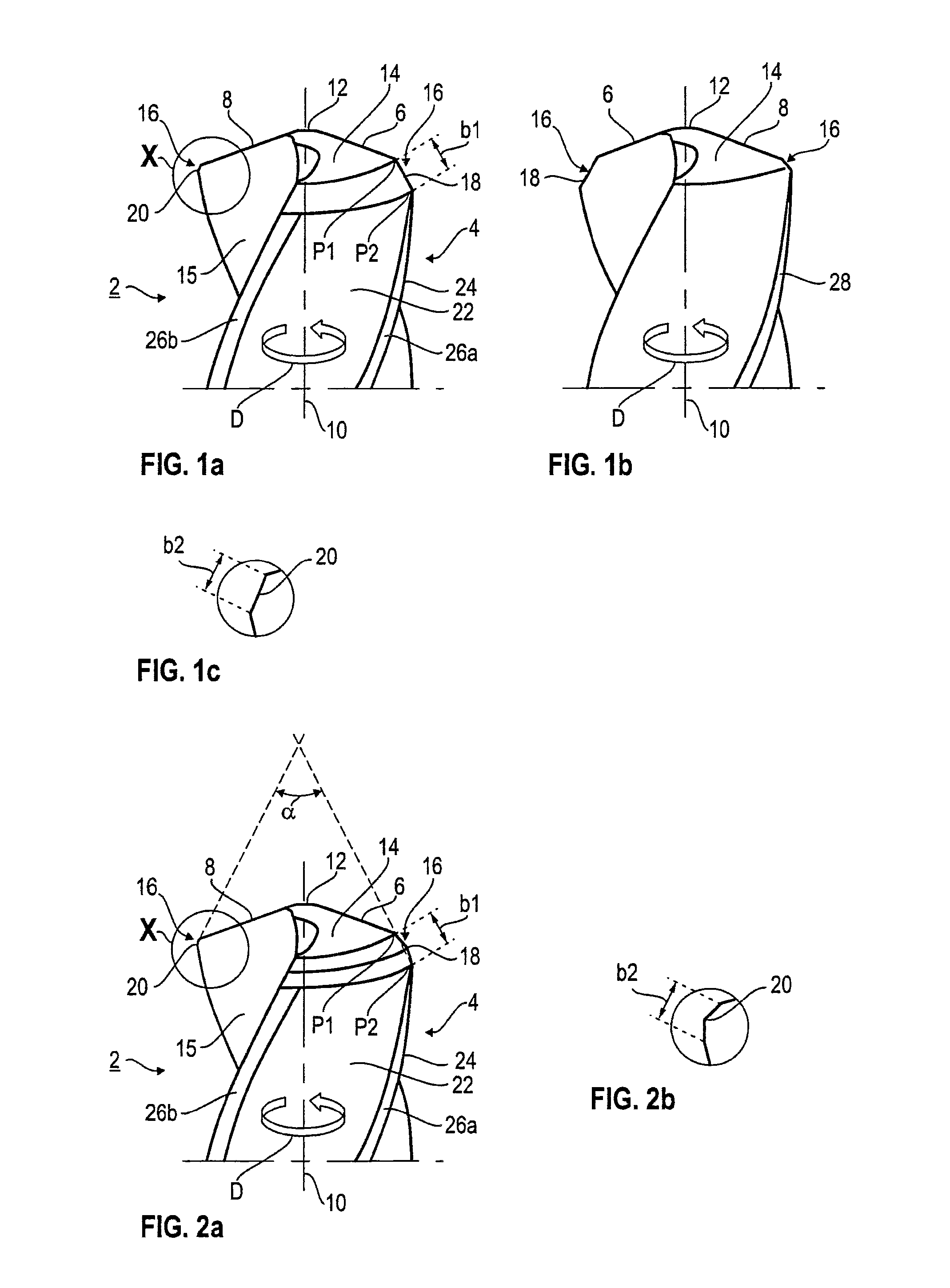
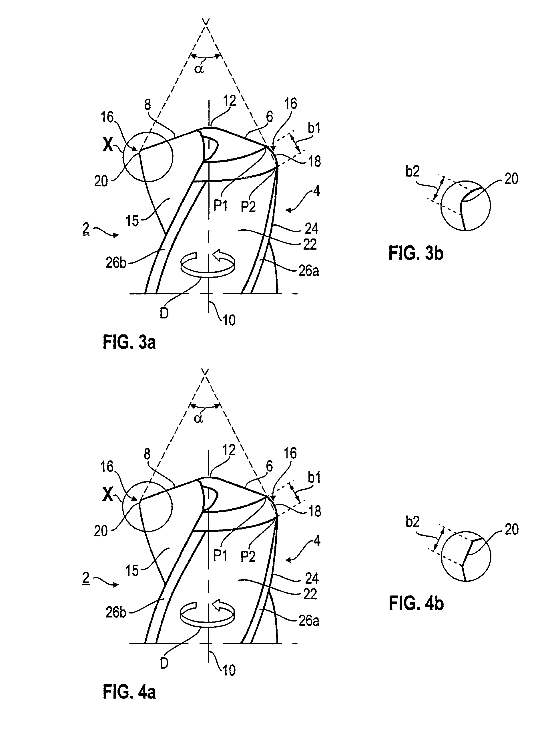
[0028]The individual details and features are explained below with reference to a rotary tool designed as a twist drill 2. The twist drill 2, only shown in sections, has, as a cutting head, a drill point 4, on which a plurality of main cutting edges 6, 8, two in the exemplary embodiment, are formed at the end face. Hereinafter, one main cutting edge is designated as guide cutting edge 6 and the other main cutting edge is designated as free cutting edge 8. The two main cutting edges 6, 8 are connected to one another via a chisel edge 12 in the region of a center axis of the drill 2, which at the same time forms a rotation axis 10. During use, the drill 2 rotates about the rotation axis 10 in rotation direction D. The drill point 4 is designed approximately in the shape of a lateral surface of a cone, such that the main cutting edges 6, 8 run obliquely outward from the chisel edge 12. A respective main flank 14 adjoins a respective main cutting edge 6, 8—as viewed in the opposite dire...


PUM

PropertyMeasurementUnit
Angleaaaaaaaaaa
Angleaaaaaaaaaa
Angleaaaaaaaaaa

Abstract

In order to provide a rotary tool, in particular a drill, with a long service life together with high-quality drill holes, particularly in the case of through bores, the invention provides a cutting head which extends along a rotational axis and has a plurality of main cutting edges which extend radially outwards and each end at a cutting corner having a corner bevel, wherein the corner bevels are of differing designs, specifically in the form of a roughing bevel and in the form of a finishing bevel.

Description

BACKGROUND OF THE INVENTION[0001]1) Field of the Invention[0002]The invention relates to a rotary tool, in particular a drill, comprising a cutting head which extends along a rotation axis and has a plurality of main cutting edges which extend radially outward and each end at the circumference of the cutting head at a cutting corner having a corner bevel.[0003]2) Description of the Related Art[0004]Such a cutting tool designed as a rotary tool can be seen, for example, from DE 202 09 767 U1.[0005]During the cutting operation, for example using drills, but also by means of reamers, milling cutters, in particular end mills, step drills, deep-hole drills or “three-lipped cutters”, there is generally the problem that the cutting corner is subjected to both high mechanical and high thermal loading in these rotary tools. In order to reduce this loading, it is known to provide “corner bevels” at the cutting corner. Due to this corner bevel, the main cutting edge does not run out rectilinea...

Claims


Application Information

Patent Timeline
IPC IPC(8): B23B51/02B23C5/10B23D77/00
CPCB23B51/02B23C5/10B23D77/00B23C2210/325B23B2251/44B23B2251/282B23B2251/248B23B2220/44B23C2210/54B23B2220/24B23B2251/14Y10T408/9097B23C2220/605Y10T408/909Y10T408/906
Inventor KAUPER, HERBERT, RUDOLF
Owner KENNAMETAL INC
Why Eureka
Try Eureka