Compression type coaxial F-connector with traveling seal and grooved post

a coaxial f-connector and traveling seal technology, applied in the field of electric connectors, can solve the problems of degrading the signal pathway between the coax, the connector, and the fitting, and the high quality f-connector is subject to demanding standards and requirements, and achieves fast and reliable connection, reliable internal seal, and high operating bandwidth

Inactive Publication Date: 2014-09-16
PERFECTVISION MFG
View PDF305 Cites 33 Cited by
  • Summary
  • Abstract
  • Description
  • Claims
  • Application Information

AI Technical Summary

Benefits of technology

[0037]This invention provides improved, axial compression type F-connectors designed to be quickly and reliably connected to coaxial cable of varying diameters and structures. The new F-connectors establish a high operating bandwidth and create reliable internal seals.

Problems solved by technology

First, typical assembly and installation of many F-connector designs is completely solderless.
High quality F-connectors are subject to demanding standards and requirements.
Modern home satellite systems distribute an extremely wide band signal, and as the demand for high definition television signals increases, and as more and more channels are added, the bandwidth requirements are becoming even more demanding.
For example, moisture and humidity can interfere with electrical contact, degrading the signal pathway between the coax, the connector, and the fitting to which it is connected.
Moisture infiltration, usually between the connector body and portions of the coaxial cable, can be detrimental.
Signal degradation, impedance mismatching, and signal loss can increase over time with subsequent corrosion.
Moisture infiltration often increases in response to mechanical imperfections resulting where coaxial compression connectors are improperly compressed.
Mechanical flaws caused by improper crimping or compression can also degrade the impedance or characteristic bandwidth of the connector, attenuating and degrading the required wide-band signal that modern TV satellite dish type receiving systems employ.
If the axial compression step does not positively lock the end cap in a proper coaxial position, the end cap can shift and the integrity of the connection can suffer.
Furthermore, particularly in modern, high-bandwidth, high-frequency applications involved with modern satellite applications distributing multiple high definition television channels, it is thought that radial deformation of internal coaxial parts, which is a natural consequence of radial compression F-connectors, potentially degrades performance.
On the other hand, some compression F connectors jam the end sleeve or cap into the body, and some force it externally.
Connector failures often result from small mechanical misalignments that result where the internal compression volume of the installation tool does not properly match the size of the captured connector.
Wear and tear over time can mismatch components.
In other words, where hand tools designed for a specific connector length are used with connectors of slightly varying sizes, as would be encountered with different types or brands of connectors, improper and incomplete closure may result.
Misdirected compression forces exerted upon the end cap or sleeve and the connector body or during compression can cause deformation and interfere with alignment.
The asymmetric forces applied by a worn or mismatched saddle type compression tool can be particularly detrimental.
Sometimes improper contact with internal grommets or O-rings results, affecting the moisture seal.
The chance that a given compression hand tool, used by a given installer, will mismatch the particular connectors in use at a given time is often increased when the connectors are of the “detent” type.
The chances that a given installer will install the requested compression F-connectors involved at a given job, or specified in a given installation contract, with the correctly sized, mating installation tool are less than perfect in reality.
Another problem is that detented F-connector, even if sized correctly and matched with the correct installation tool, may not install properly unless the installer always exerts the right force by fully deflecting the tool handles.
Even if a given installation tool is designed for the precise dimensions of the connectors chosen for a given job, wear and tear over the life of the hand tool can degrade its working dimensions and tolerances.
If and when the chosen compression tool is not correctly matched to the F-connector, deformation and damage can occur during installation, particularly with detented compression F-connectors.
Another problem occurs where an installer improperly positions the connector within the hand tool.
Repetition and lack of attention tends to breed sloppiness and carelessness.
Improper alignment and connector placement that can cause axial deformation.
Sloppiness in preparing a cable end for the connector can also be detrimental.
Despite numerous attempts to improve F-connectors, as evidenced in part by the large number of existing patents related to such connectors, a substantial problem with internal sealing still exists.

Method used


Image

  • Compression type coaxial F-connector with traveling seal and grooved post
  • Compression type coaxial F-connector with traveling seal and grooved post
  • Compression type coaxial F-connector with traveling seal and grooved post

Examples


Embodiment Construction

[0081]For purposes of disclosure the entire disclosure within U.S. utility patent application entitled “Compression Type Coaxial Cable F-Connectors with Traveling Seal and Barbless Post,” filed Nov. 15, 2010, Ser. No. 12 / 927,424, and U.S. Pat. Nos. 7,841,896 and 7,513,795 are hereby incorporated by reference as if fully set forth herein.

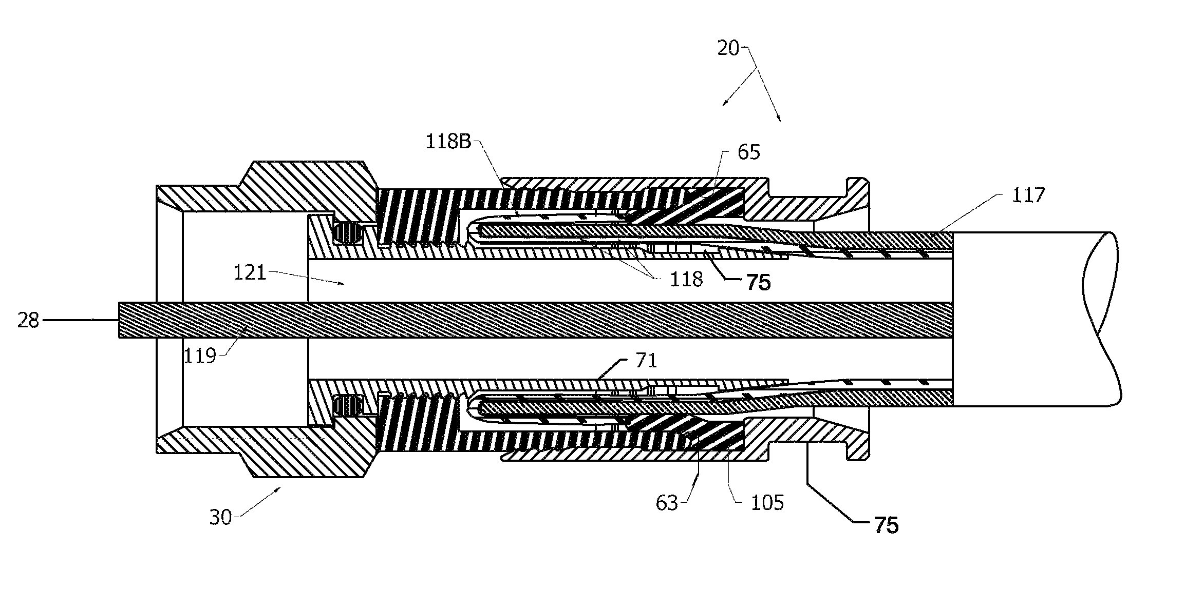
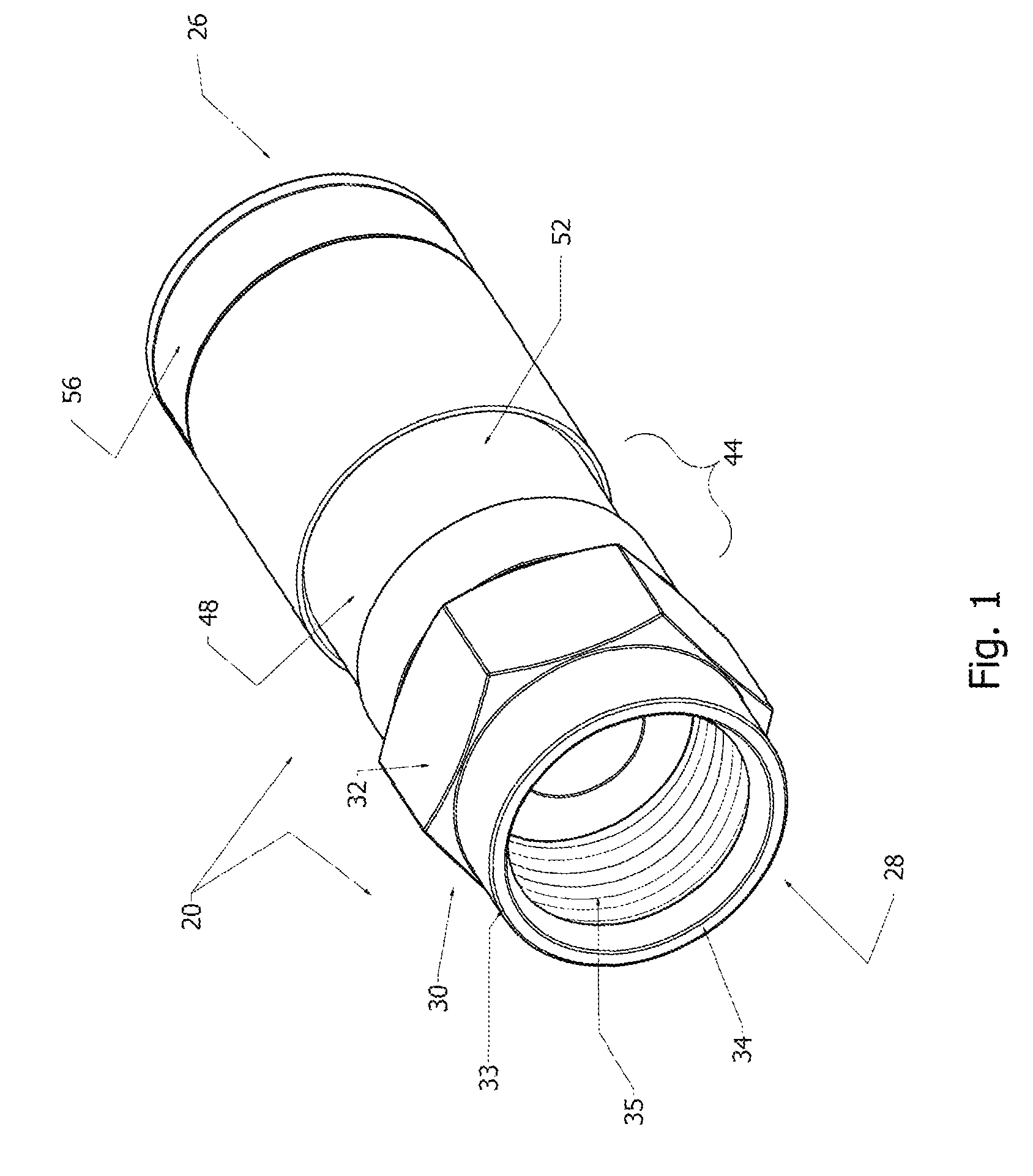
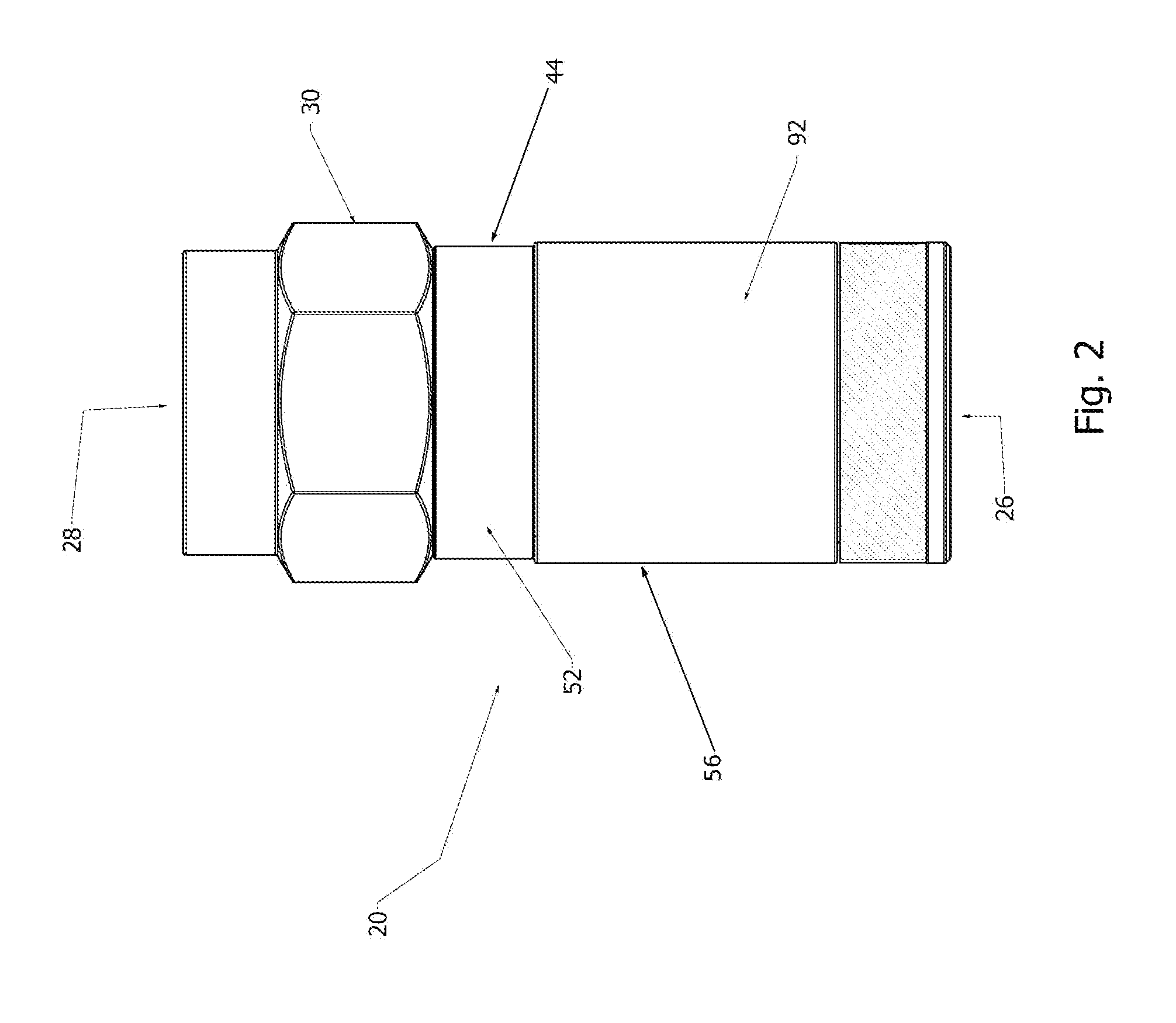
[0082]With initial reference directed to FIGS. 1-5 of the appended drawings, an open F-connector for coaxial cable constructed generally in accordance with the preferred embodiment of the invention has been generally designated by the reference numeral 20. The same connector disposed in a closed position is designated 21 (i.e., FIGS. 6-8). Connectors 20 and 21 are adapted to terminate an end of properly prepared coaxial cable, the proper preparation of which is well recognized by installers and others with skill in the art. After a prepared end of coaxial cable is properly inserted through the open bottom end 26 (FIG. 1) of an open connector 20, the ...


PUM


Abstract

Axially compressible, self-sealing, high bandwidth F-connectors for conventional hand tools for interconnection with coaxial cable. An internal, dual segment sealing grommet activated by compression elongates and deforms to provide a travelling seal. Each connector has a rigid nut that is rotatably secured to a, tubular body. A rigid, conductive post has a barbless shank with a groove that coaxially extends through the connector and penetrates the coaxial cable within the connector. A tubular, metallic end cap is slidably fitted to a body shank, and is thereafter forcibly compressed lengthwise during installation. The end cap has a ring groove for seating the enhanced grommet. The grommet travels and extrudes during compression to mate and intermingle with a portion of the cable braid that is looped back from a prepared cable end, and portions of the cable are urged towards the post groove for sealing.

Description

CROSS REFERENCE TO RELATED APPLICATION[0001]This is a Continuation-in-Part application based upon a prior U.S. utility patent application entitled “Compression Type Coaxial Cable F-Connectors with Traveling Seal and Barbless Post,” filed Nov. 15, 2010, Ser. No. 12 / 927,424, which was a Continuation-in-Part application based upon a prior U.S. utility patent application entitled “Sealed Compression Type Coaxial Cable F-Connectors,” filed Feb. 26, 2009, Ser. No. 12 / 380,327, now U.S. Pat. No. 7,841,896, issued Nov. 30, 2010, which was a Continuation-in-Part of an application entitled “Compression Type Coaxial Cable F-Connectors,” Ser. No. 12 / 002,261, filed Dec. 17, 2007, now U.S. Pat. No. 7,513,795, issued Apr. 7, 2009.BACKGROUND OF THE INVENTION[0002]1. Field of the Invention[0003]The present invention relates generally to electrical connectors for coaxial cables and related electrical fittings. More particularly, the present invention relates to coaxial F-connectors of the axial compre...

Claims


Application Information

Patent Timeline
Patent Type & Authority Patents(United States)
IPC IPC(8): H01R9/05H01R13/46H01R13/52H01R101/00
CPCH01R13/46H01R13/5205H01R9/0524H01R2101/00
Inventor SHAW, GLEN, DAVID
Owner PERFECTVISION MFG
Why Eureka
Try Eureka