
Drying apparatus and methods and accessories for use therewith

a drying apparatus and accessory technology, applied in the direction of lighting and heating apparatus, electric/magnetic/electromagnetic heating, furnaces, etc., can solve the problems of uneven heating, inconvenient use of energy, so as to improve the net power and/or efficiency and/or uniformity of energy transfer, the frequency of inputs is substantially different, and the effect of increasing the flexibility of providing power

Active Publication Date: 2014-09-23
BORA APPLIANCES +1
View PDF268 Cites 89 Cited by
  • Summary
  • Abstract
  • Description
  • Claims
  • Application Information

AI Technical Summary

Benefits of technology

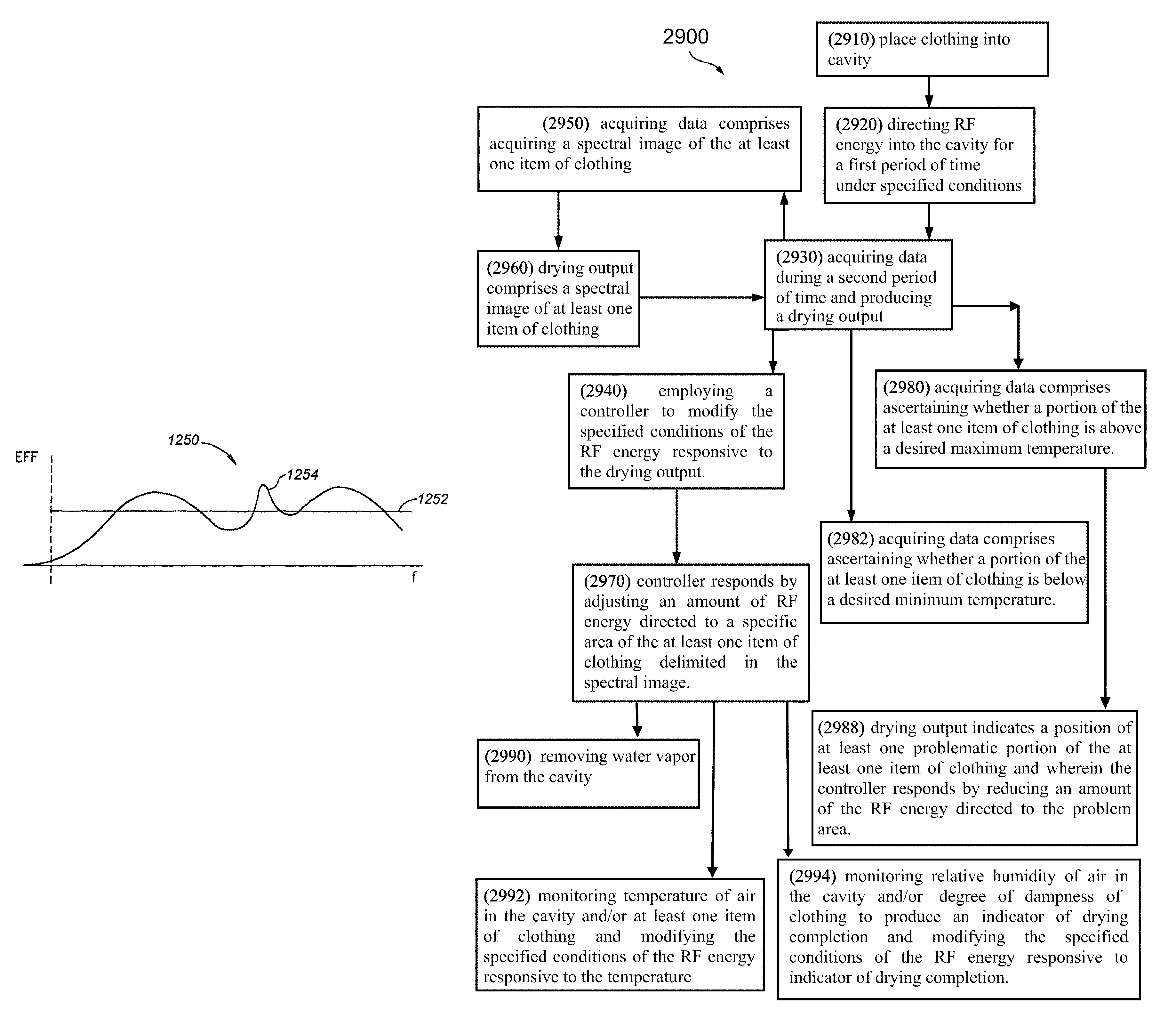
The invention uses RF energy to dry items of clothing without heating the fabric significantly for a long time. This helps increase the lifespan of the garment. The RF energy heats the water that is present in the garment, which in turn heats the fabric indirectly. The use of specific RF frequencies ensures that only water is heated, reducing the amount of energy needed for the drying process. The heat transferred to the fabric can also return to the water as it evaporates.

Problems solved by technology

Typically, condensation conventional condensation dryers use more energy and take longer to dry fabric than vented dryers.
However, its limitations are well known.
These include, for example uneven heating and slow absorption of heat, especially for defrosting.
Because of the difficulties of such analysis, such analysis has only been carried out on regular shapes, such as spherical, and ellipsoidal shapes.
Experimental attempts have apparently been made on kidney sized specimens, but results of these experiments do not indicate that a viable solution for defrosting kidneys is available.
Moreover, there does not appear to be a solution for defrosting other organs or foods of more arbitrary shapes.

Method used


Image

  • Drying apparatus and methods and accessories for use therewith
  • Drying apparatus and methods and accessories for use therewith
  • Drying apparatus and methods and accessories for use therewith

Examples


first embodiment

[0647]In the invention, the maximum net power efficiency for each port is maximized, in the sense, that the net power efficiency at a point of maximum efficiency within the sweep range is made as high as possible. The efficiency and the frequency at which the efficiency is a maximum is noted. Optionally, the width of the efficiency peak and a Q-factor are noted as well.

second embodiment

[0648]the invention is based on a similar criterion. For this embodiment the area under each resonance peak of the net efficiency of transfer is determined. This area should be a maximum. The efficiency, the center frequency of the resonance having the maximum area and its width are noted.

[0649]In an embodiment of the invention, the criteria for determining if the variables are properly set is when the peak net efficiency (first embodiment) or the area or a width (second embodiment) is above some predetermined level or a Q-factor is below some predetermined level. For example, there may be a restriction that the area above 60% net efficiency is maximized for each of the feeds.

[0650]It is noted that energy that is neither reflected nor transmitted to the other ports is absorbed either in the walls of the cavity or in the object being heated. Since absorption in the conducting walls is much lower than that in the object by a large factor, the net efficiency is approximated by the prop...


PUM


Abstract

A method of drying an object comprising, providing an object into an RF cavity; applying broadband RF energy to the object in controlled manner which keeps the object within a desired temporal temperature schedule and within a desired spatial profile; and terminating the drying when it is at least estimated that a desired drying level is achieved.

Description

RELATED APPLICATIONS[0001]This application is a National Phase of PCT Patent Application No. PCT / IL2008 / 000231 having International filing date of Feb. 21, 2008, which is a continuation-in-part (CIP) of PCT Patent Application No. PCT / IL2007 / 000864 having International filing date of Jul. 10, 2007, which is a continuation-in-part (CIP) of PCT / IL2007 / 000235 having International filing date of Feb. 21, 2007, which claims the benefit of priority of U.S. Provisional Patent Application Nos. 60 / 806,860 filed on Jul. 10, 2006, and 60 / 775,231 filed on Feb. 21, 2006.[0002]PCT Patent Application No. PCT / IL2007 / 000864 also claims the benefit of priority of U.S. Provisional Patent Application Nos. 60 / 924,555 filed on May 21, 2007 and 60 / 806,860 filed on Jul. 10, 2006.[0003]PCT Patent Application No. PCT / IL2008 / 000231 is also a continuation-in-part (CIP) of PCT / IL2007 / 000236 having International filing date of Feb. 21, 2007, which claims the benefit of priority of U.S. Provisional Patent Applicat...

Claims


Application Information

Patent Timeline
Patent Type & Authority Patents(United States)
IPC IPC(8): F26B3/347D06F58/26
CPCD06F58/266F26B3/347H05B6/705H05B2206/045F26B3/28H05B6/72H05B6/645H05B6/6464H05B6/6479H05B6/6458H05B6/80H05B2206/046D06F2103/52D06F2103/64D06F2105/28
Inventor BEN-SHMUEL, ERANATZMONY, DANIELLASHAHAM, GINADIBILCHINSKY, ALEXANDER
Owner BORA APPLIANCES
Learn More