Electronic device for average current mode DC-DC conversion

a technology of dc-dc and converter, applied in the direction of dc-dc conversion, power conversion system, instruments, etc., can solve the problem of limited bandwidth of the response at the output node of the dc-dc converter

Active Publication Date: 2014-09-23
TEXAS INSTR INC
View PDF3 Cites 7 Cited by
  • Summary
  • Abstract
  • Description
  • Claims
  • Application Information

AI Technical Summary

Benefits of technology

[0005]It is a general object of the invention to provide an electronic device for DC-DC conversion that can adjust the output voltage without being constrained by the bandwidth of the control loop of the DC-DC converter.
[0008]According to an aspect of the invention, the first reference voltage may be derived from the control voltage using a first resistive voltage divider. The second reference voltage may be derived from the control voltage using a second resistive voltage divider. This aspect of the invention provides a simple mechanism to keep the first reference voltage proportional to the second reference voltage and to control both voltages with the single control voltage. If the second resistive voltage divider is coupled to the second side of the second capacitor, the duty cycle is immediately set close to the correct value. The current and voltage control loops still operate properly and provide the required accuracy of the output voltage.

Problems solved by technology

In both cases, the response at the output node of the DC-DC converter is limited by the bandwidth of the control loop of the DC-DC converter.

Method used


Image

  • Electronic device for average current mode DC-DC conversion
  • Electronic device for average current mode DC-DC conversion

Examples


Embodiment Construction

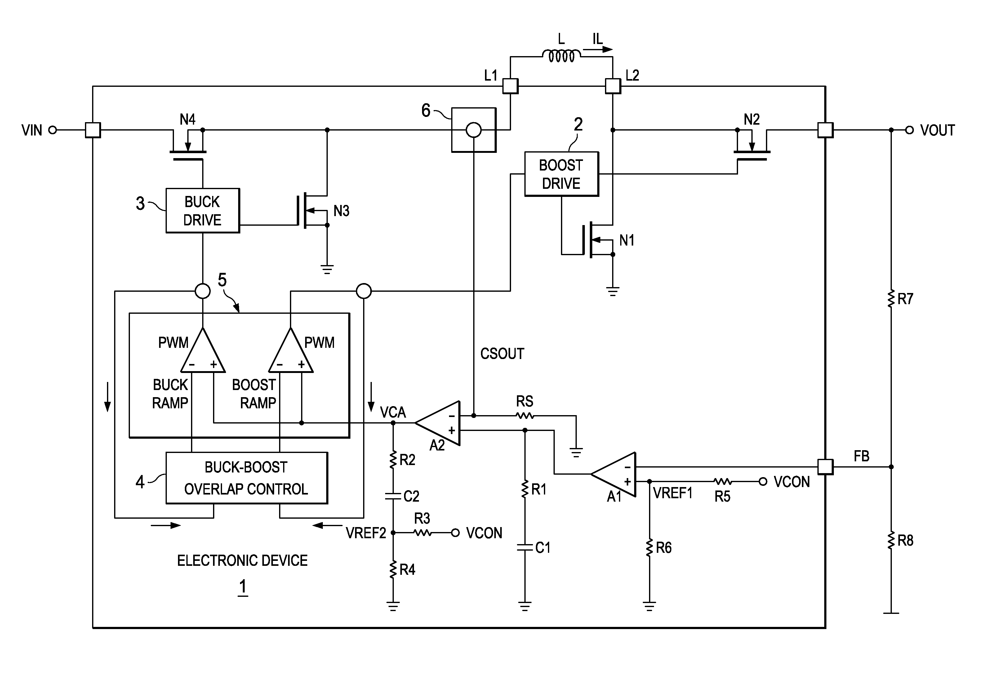
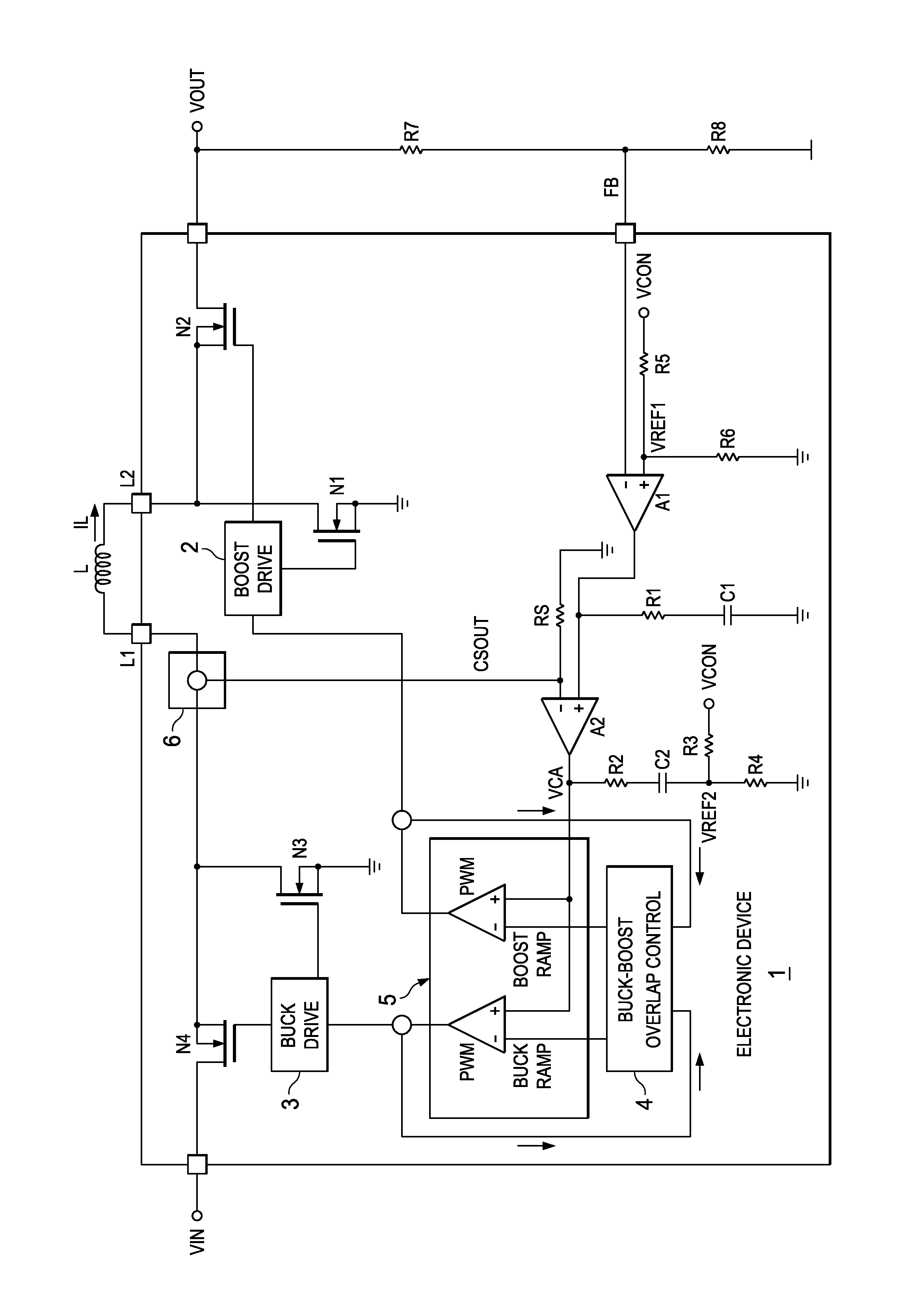
[0013]FIG. 1 shows a simplified circuit diagram of an electronic device according to an embodiment of the invention. The electronic device 1, is an integrated semiconductor circuit. The solid line marks the limit of the integrated electronic device 1. However, parts which are shown outside the solid line may also be incorporated in the electronic device 1 in other embodiments.

[0014]The electronic device 1 includes several main components for implementing a buck-boost DC-DC converter in order to convert an input voltage VIN into an output voltage VOUT. However, the invention can also be applied to buck converters or boost converters or other types of DC-DC converters. The electronic deivce 1 comprises a first transconductance amplifier A1, a second transconductance amplifier A2, a boost-mode driving stage 2, a buck-mode driving stage 3, a buck-boost overlap control stage 4, a current ramp control stage 5 and a current sensing stage 6. Furthermore, there are two pairs of switches N1, ...


PUM


Abstract

An average current mode buck-boost DC to DC converter has a buck stage coupled between an input voltage source terminal and an output terminal. A boost stage is coupled between the input voltage source terminal and the output terminal. A current ramp control circuit generates a ramp signal for driving the buck and boost stages, the ramp signals being coupled to the buck and boost stages. A constant voltage related to the desired output voltage by a constant is applied directly to both a voltage control feedback loop for adjusting the output voltage and directly to an input to the current ramp control circuit, whereby the output voltage can be shifted from one voltage to another by feedforward control.

Description

FIELD OF THE INVENTION[0001]The invention relates to an electronic device for DC-DC conversion, and more specifically to an electronic device for buck, boost or buck-boost DC-DC conversion using an average current mode.BACKGROUND OF THE INVENTION[0002]High efficiency single inductor buck-boost DC-DC converters are well known in the art. An example of these types of DC-DC converters are the integrated semiconductor electronic devices of the TPS630xx series of Texas Instruments, which provide a power supply solution for products powered by either a two-cell or three-cell alkaline, NiCd or NiMH battery, or a one-cell Li-ion or Li-polymer battery. Output currents can go as high as 3 A, while using a single-cell Li-ion or Li-polymer battery and discharge it down to 2.5 V or lower. This known type of buck-boost converters is based on a fixed frequency, pulse-width-modulation (PWM) controller using synchronous rectification to obtain maximum efficiency. At low load currents, the converter ...

Claims


Application Information

Patent Timeline
Patent Type & Authority Patents(United States)
IPC IPC(8): G05F1/00
CPCH02M3/1582H02M3/158
Inventor PREXL, FRANZNEUHAEUSLER, JUERGEN
Owner TEXAS INSTR INC
Why Eureka
Try Eureka