Method for reducing differential shrinkage in stereolithography

a stereolithography and differential shrinkage technology, applied in the field of stereolithography method and system, can solve the problems of differential shrinkage, distortion of cad designed dimensions of objects built using stereolithography, polymerization and hardening of resin on illuminated areas, etc., to achieve large reproduction accuracy, reduce differential shrinkage, and increase strength

Inactive Publication Date: 2014-09-30
MATERIALISE NV
View PDF23 Cites 4 Cited by
  • Summary
  • Abstract
  • Description
  • Claims
  • Application Information

AI Technical Summary

Benefits of technology

[0008]The present invention provides a new and improved stereolithography method and system for generating a three-dimensional object by forming successive, adjacent, cross-sectional laminae of that object out of a resin capable of altering its physical state in response to stimulation or illumination. The methods and tools of the present invention allow the generation of objects with reduced differential shrinkage and increased strength and with a large accuracy of reproduction.
[0009]It has been found that beside the geometry of the successive layers, parameters such as the stimulation power and pre-stimulation waiting time play a crucial role in minimizing differential shrinkage. Moreover, altering these parameters does not require complex redesign of the building nor of the preparation software as do other solutions and can therefore easily be incorporated into any existing software. Moreover the modulation of these parameters in the methods according to the invention leaves no visible markings on the parts nor does it have any negative effects on overall part quality.

Problems solved by technology

Secondly the sections of the building area that are part of the object to be constructed are illuminated, thereby causing the resin on the illuminated areas to polymerize and harden.
However, objects built using stereolithography have a tendency to distort from their CAD designed dimensions.
Differential shrinkage is one of the most disturbing flaws often detected in many parts fabricated by stereolithograpy.
Moreover certain geometries or sections in a part are more susceptible than others.
Especially large flat surfaces are susceptible to shrinkage.
For instance a large flat surface connecting to thin upright structures can lead to significant part deformation.
Several of these techniques are based on a non-standard way of illuminating the areas to be polymerized.
This however requires a complex redesign of the slicing and hatching software, leading to visible markings on the outside of the parts and negatively influencing quality of the part.
Moreover these techniques also result in a slower construction time.
This therefore requires complex redesign of both building and preparation software, leading to a slower production time and reduction of the quality of the produced parts.

Method used


Image

  • Method for reducing differential shrinkage in stereolithography
  • Method for reducing differential shrinkage in stereolithography
  • Method for reducing differential shrinkage in stereolithography

Examples


example 1

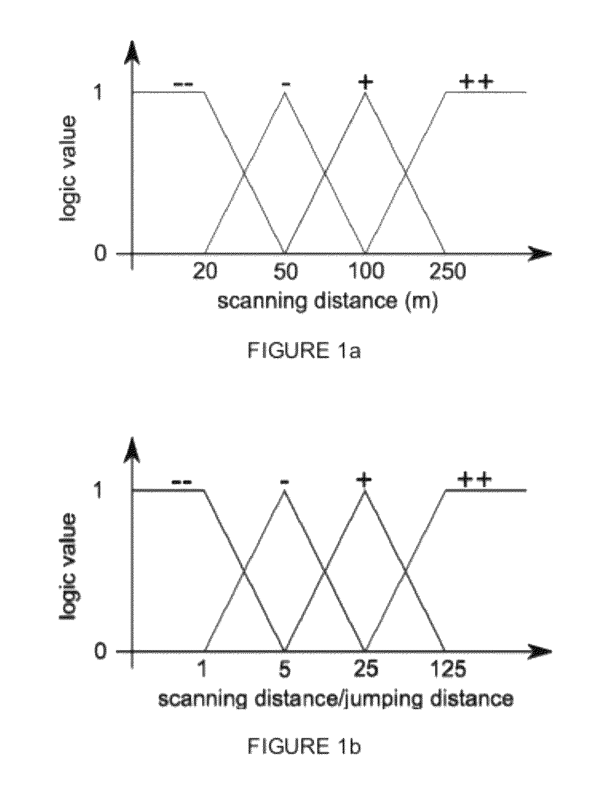
[0157]The present example describes a particular embodiment according to the present invention wherein the pre-stimulation waiting time (Tp) is determined according to Formula II for a P equal to Pref and a resin scaling factor of 1 and wherein Tst is determined by the following fuzzy system:

[0158]

TABLE 1Scan distance logic valueVery highHighLowVery lowRatio of Scan distance overVery++++++jump distance logic valvehighHigh++00Low−00−Very−−−−−−−−low

[0159]Wherein the Fuzzy logic value corresponds with:

[0160]

TABLE 2Fuzzy+++0−−−Time (s)30201050

[0161]The matrix is to be interpreted as:

[0162]If the scan distance logic value is very high and the ratio of scan distance over jump distance is very high then the time is ++, if the scan distance is high and the ratio of scan distance over jump distance is very high then the time is ++, if the scan distance is low and the ratio of scan distance over jump distance is very high then the time is +, . . . .

[0163]The relation between the fuzzy logic v...

example 2

[0164]To aid the understanding of the present invention and to show the strengths of the system, several example geometries are presented for which the pre-stimulation waiting time to be used for the next layer is calculated according to example 1 and assuming all layers are built using a fixed stimulation power. Four geometries are used and for one of the geometries two separate vector types have been used (skin fill and hatching).

[0165]

TABLE 3Geometry200 × 200200 × 20010 × 20040 × 5010 × 10mmmmmmmmmmSkin fillHatchHatchHatchHatchPre-stimulation603012.914.30time (s)

[0166]As can be seen areas susceptible to differential shrinkage are identified and give rise to increased waiting times.

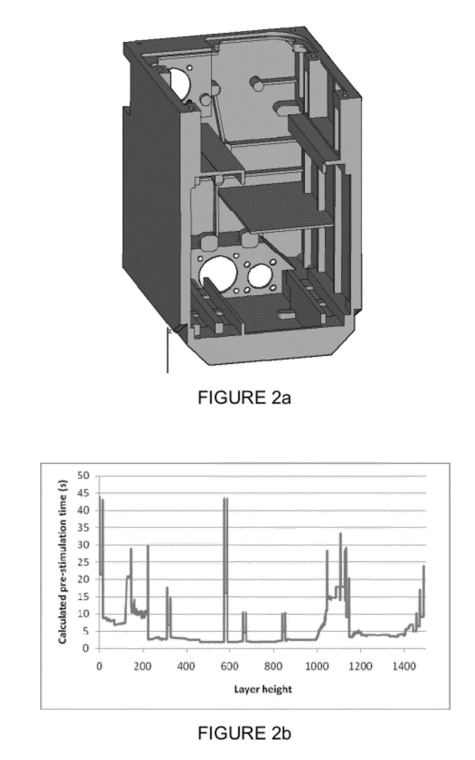
[0167]Whereas for simple geometries a person skilled in the art might assign several ranges of pre-stimulation waiting times, for complex parts individually determined pre-stimulation waiting times covering a continuous range of possible times cannot be obtained in this way. An example of such complex p...

example 3

[0168]Analogous to example 2 several example geometries are presented for which the suggested stimulation powers to be used in this layer are calculated assuming fixed pre-stimulation waiting times for all layers.

[0169]

TABLE 4Geometry200 × 200200 × 20010 × 20040 × 50mmmmmmmm10 × 10 mmSkin fillHatchHatchHatchHatchStimulation50100218194500power (mW)

[0170]For the complex part shown in FIG. 2a the stimulation powers for all of the individual layers of the example part are shown in FIG. 2c assuming a fixed pre-stimulation waiting time for all layers.


PUM

PropertyMeasurementUnit
timeaaaaaaaaaa
timeaaaaaaaaaa
shrinkageaaaaaaaaaa

Abstract

The present invention relates to a new and improved stereolithography method and system for generating a three-dimensional object by forming successive, adjacent, cross-sectional laminae of that object, thereby providing an object being specially processed to reduce differential shrinkage.

Description

CROSS-REFERENCE TO RELATED APPLICATION[0001]This application claims the benefit of U.S. Provisional Patent Application No. 61 / 386,652, filed on Sep. 27, 2010 and GB Patent Application No. 1016169.3, filed Sep. 27, 2010, the contents of which are herein incorporated by reference in their entireties.FIELD OF THE INVENTION[0002]The present invention relates to a new and improved stereolithography method and system for generating a three-dimensional object by forming successive, adjacent, cross-sectional laminae of that object, thereby providing an object being specially processed to reduce differential shrinkage.BACKGROUND OF THE INVENTION[0003]Stereolithography is a technique that belongs to the family of rapid prototyping and manufacturing techniques. Generally these techniques allow the fabrication of three-dimensional objects directly starting from computer generated CAD files. In stereolithography the parts are first divided into a stack of successive layers that represents the th...

Claims


Application Information

Patent Timeline
Patent Type & Authority Patents(United States)
IPC IPC(8): B29C35/08B29C41/02B29C71/04B29C67/00
CPCB29C67/0085B29C67/0066B29C67/0088B29K2995/0096B33Y10/00B33Y30/00B33Y50/00B29C64/124B29C64/268B29C64/393
Inventor COECK, SAM
Owner MATERIALISE NV
Why Eureka
Try Eureka