
Fuel-injection condition detector

a condition detector and fuel injection technology, applied in the direction of machines/engines, electrical control, instruments, etc., can solve the problems of high accuracy, difficult to compute the fuel injection-start timing “r”, and high correlation, and achieve high correlation and high accuracy

Active Publication Date: 2014-09-30
DENSO CORP
View PDF11 Cites 4 Cited by
  • Summary
  • Abstract
  • Description
  • Claims
  • Application Information

AI Technical Summary

Benefits of technology

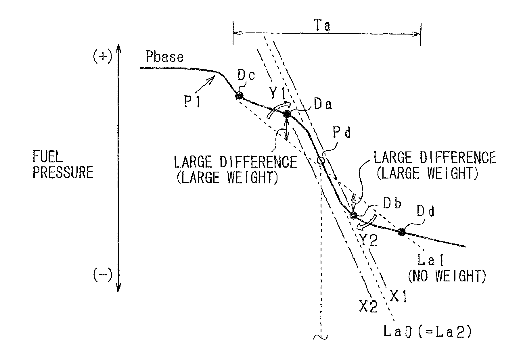
The system achieves high accuracy in estimating fuel-injection conditions by obtaining weighted approximate lines that closely match the tangential lines, thereby improving the precision of fuel-injection start and end timings and maximum injection rates.

Problems solved by technology

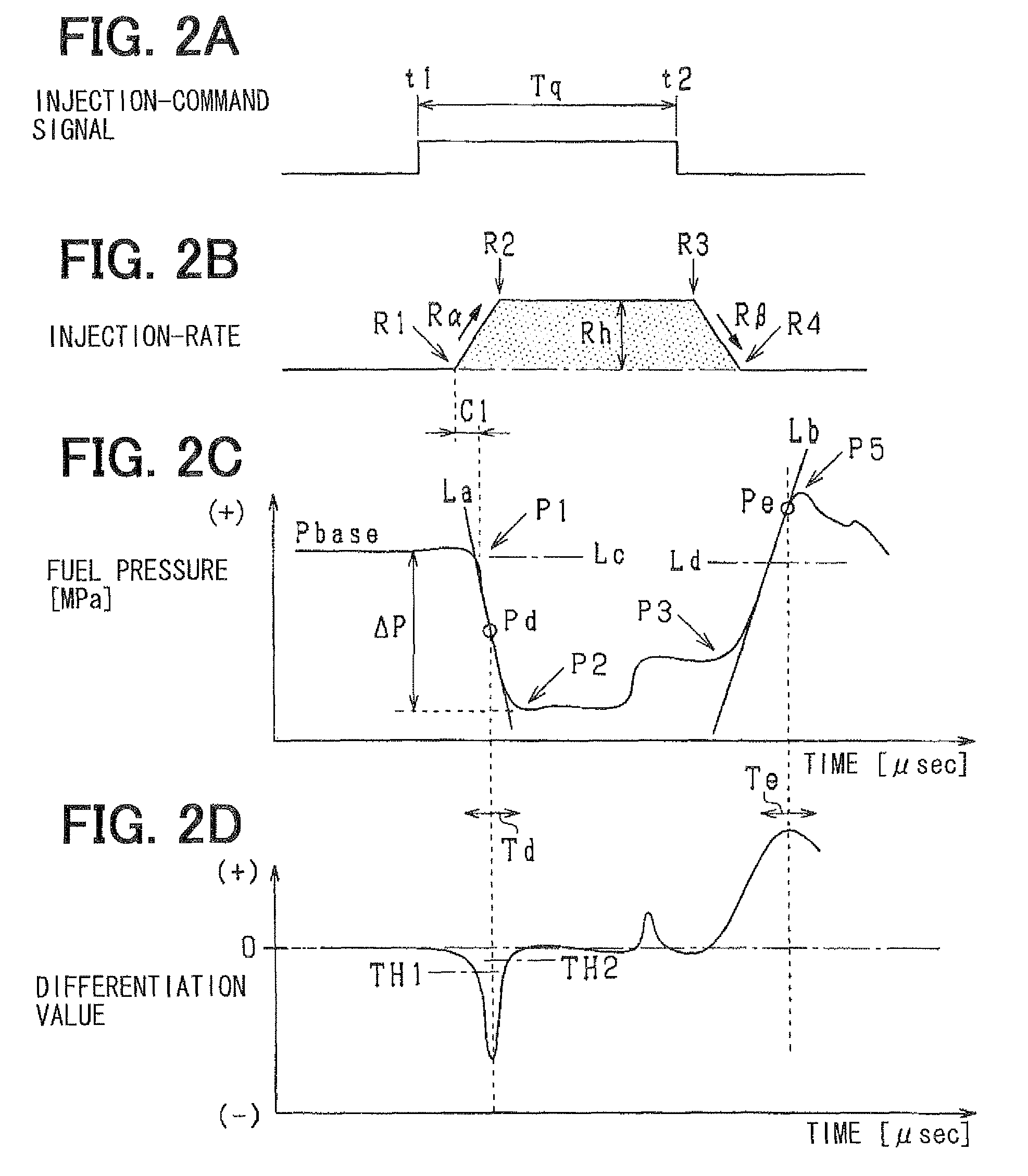
Therefore, it is difficult to compute the fuel-injection-start timing “R1” with high accuracy.
Thus, it is difficult to compute the fuel-injection-end timing “R4” with high accuracy.
However, also in this case, since the lines “La” and “Lb” may deviate, it is difficult to compute the fuel-injection condition with high accuracy.

Method used


Image

  • Fuel-injection condition detector
  • Fuel-injection condition detector
  • Fuel-injection condition detector

Examples


first embodiment

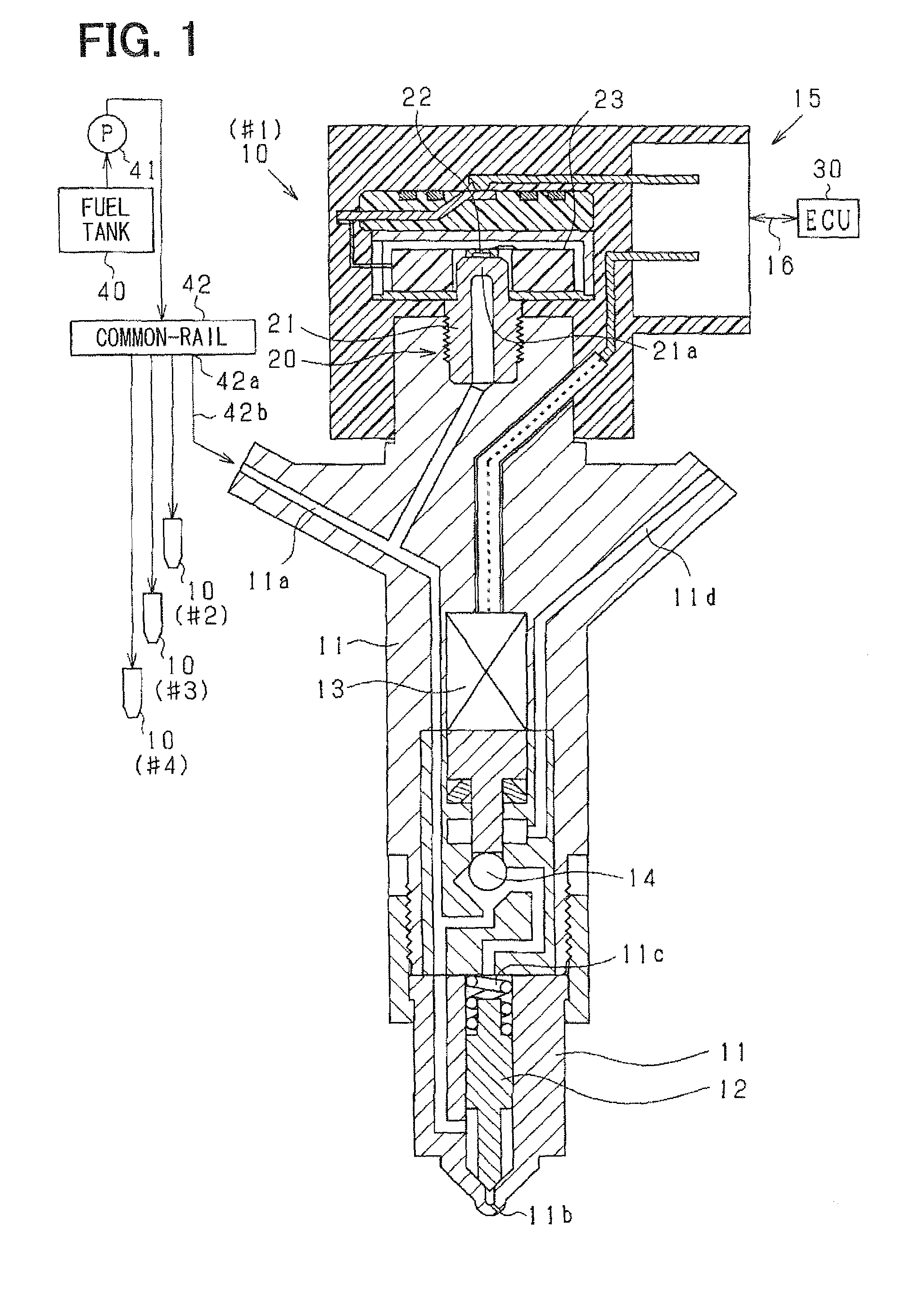
[0038]FIG. 1 is a schematic view showing fuel injectors 10 provided to each cylinder, a fuel pressure sensor 20 provided to each fuel injectors 10, an electronic control unit (ECU) 30 and the like.

[0039]First, a fuel injection system of the engine including the fuel injector 10 will be explained. A fuel in a fuel tank 40 is pumped up by a high-pressure pump 41 and is accumulated in a common-rail (accumulator) 42 to be supplied to each fuel injector 10 (#1-#4). The fuel injectors 10 (#1-#4) perform fuel injection sequentially in a predetermined order. The high-pressure pump 41 is a plunger pump which intermittently discharges high-pressure fuel.

[0040]The fuel injector 10 is comprised of a body 11, a needle valve body 12, an actuator 13 and the like. The body 11 defines a high-pressure passage 11a and an injection port 11b. The needle valve body 12 is accommodated in the body 11 to open / close the injection port 11b.

[0041]The body 11 defines a backpressure chamber 11c with which the h...

second embodiment

[0072]In the above first embodiment, the weights “w1”-“w11” are computed based on the differences “e1”-“e11” in step S23. According to the second embodiment, the weights “w1”-“w11” are computed based on a time difference between a detection timing of each pressure value “D1”-“D11” and an appearance timing “tPd” of the point “Pd”. In FIG. 6, the weights of the values “D5” and “D6” are greater than those of values “D1”, “D2”, “D10” and “D11”. In FIG. 5A, the weights of the values “Da” and “Db” are greater than those of the values “Dc” and “Dd”.

[0073]FIG. 7 is a flowchart showing a processing for computing an approximated line of a descent pressure waveform. In step S21 and step S22, the pressure values “D1”-“D11” of the descent pressure waveform are approximated to a least-squares approximate line “La1” by least squares method.

[0074]In step S23a (weighting means), the appearance timing “tPd” of the point “Pd” is computed. In step S23b (weighting means), with respect to each value “D1”...


PUM


Abstract

A fuel-injection condition detector includes a first approximate portion which approximates a plurality of fuel pressure values representing the descent pressure waveform or the ascent pressure waveform into a least-squares approximate line by least-squares method; and a weighting portion which applies a weight to the fuel pressure value. The weight is set greater as a difference between the fuel pressure and the least-squares approximate line is larger. Then, the weighted values are approximated into a weighted approximate line by the least-squares method.

Description

CROSS-REFERENCE TO RELATED APPLICATION[0001]This application is based on Japanese Patent Application No. 2010-209100 filed on Sep. 17, 2010, the disclosure of which is incorporated herein by reference.FIELD OF THE INVENTION[0002]The present invention relates to a fuel-injection condition detector which detects a variation in fuel pressure due to a fuel injection through a fuel injector provided to an internal combustion engine, and then estimates a fuel-injection condition, such as a fuel-injection-start timing and a fuel-injection-end timing, based on a pressure waveform detected by a fuel pressure sensor.BACKGROUND OF THE INVENTION[0003]JP-2009-97385A shows a fuel-injection condition detector which detects a variation in fuel pressure due to a fuel injection by means of a fuel pressure sensor, and then estimates a fuel-injection condition, such as a fuel-injection-start timing and a fuel-injection-end timing, based on a pressure waveform detected by a fuel pressure sensor. The pre...

Claims


Application Information

Patent Timeline
Patent Type & Authority Patents(United States)
IPC IPC(8): G01F23/14F02D41/38
CPCF02D41/3863F02D2250/04F02D2200/0604F02D2200/0602
Inventor TAKASHIMA, YOSHIMITSU
Owner DENSO CORP
Learn More