Multi discharging tube plasma reactor
a plasma reactor and discharging tube technology, which is applied in the direction of plasma technique, electric discharge lamps, electric lighting sources, etc., can solve the problems of insufficient response of plasma sources or inductively coupled plasma sources to demands, damage to the inside of the reactor body, and difficulty in maintaining the ignited plasma at a low voltage environmen
- Summary
- Abstract
- Description
- Claims
- Application Information
AI Technical Summary
Benefits of technology
Problems solved by technology
Method used
Image

Examples
first embodiment
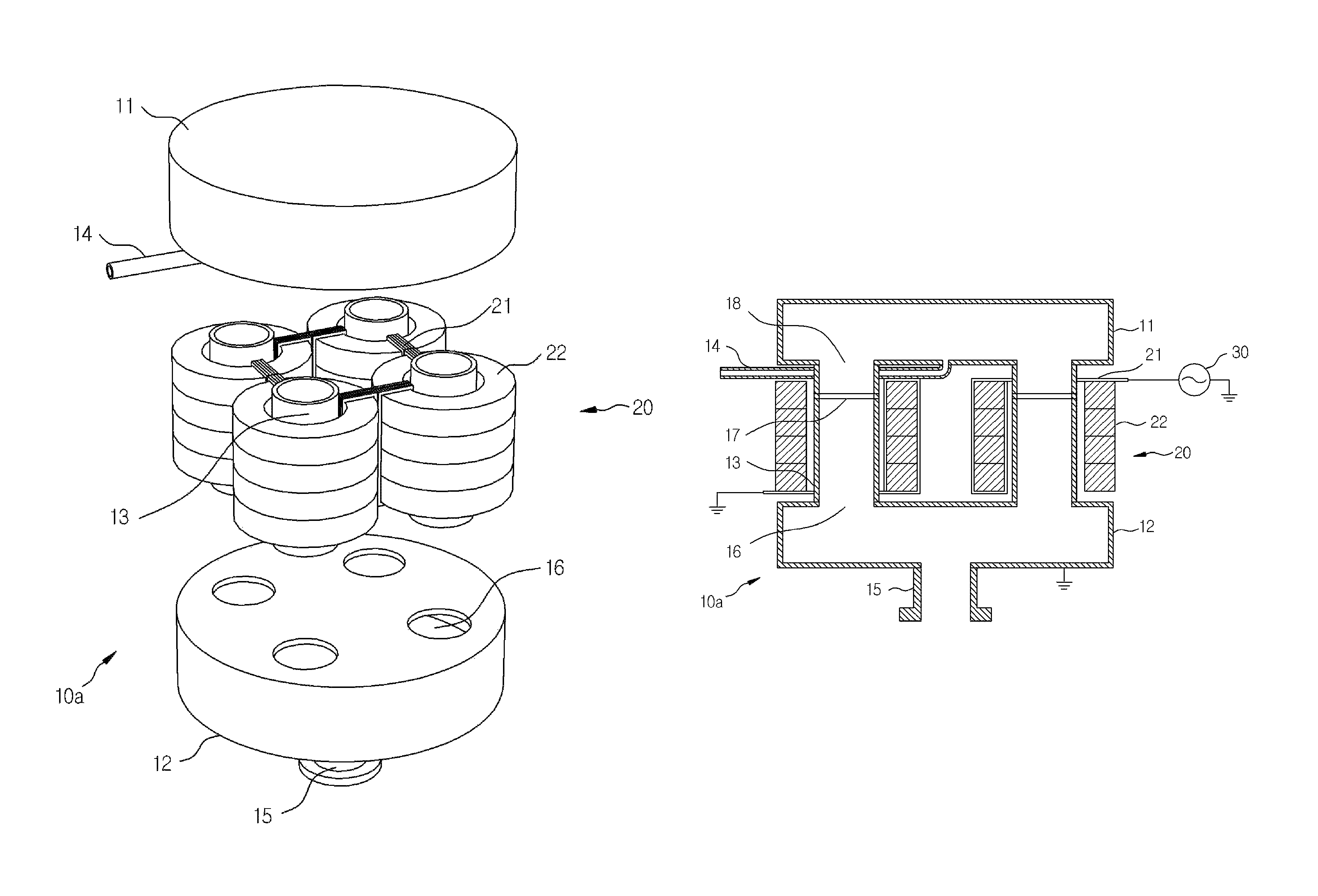
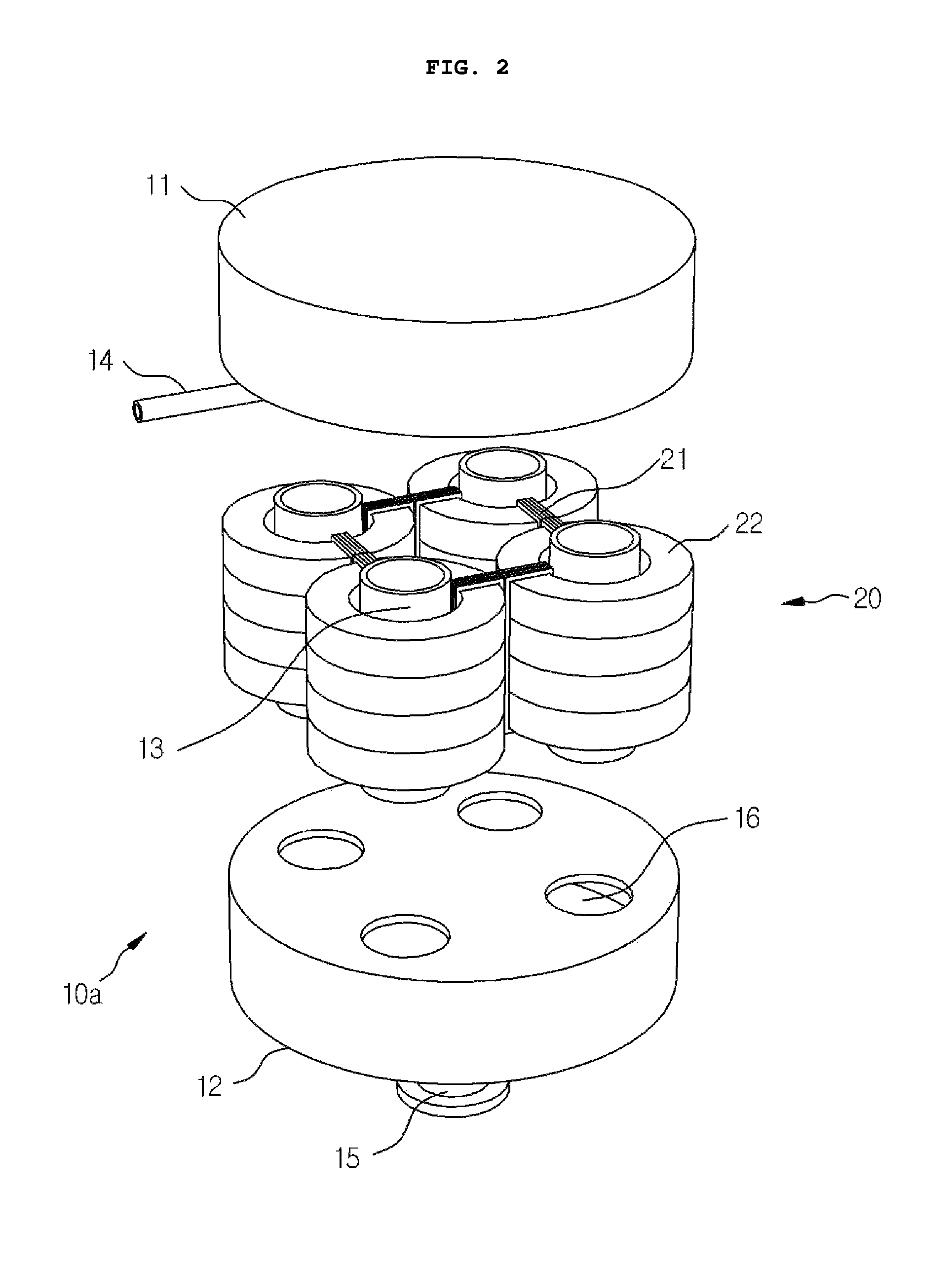
[0086]A multi discharging tube plasma reactor 10a according to the present invention, as shown in FIGS. 2 to 4, supplies remotely plasma gas to the process chamber 40. The plasma reactor 10a is provided with multi discharging tubes of an upper discharging tube 11, a lower discharging tube 12 and a plurality of discharging tube bridges 13. For example, four discharging tube bridges 13 provide a plurality of discharging channels by coupling an upper opening 18 of the upper discharging tube 11 and a lower opening 16 of the lower discharging tube 12. Here, the magnetic cores 22 each having the first winding coil 21 are equipped to the plurality of discharging tube bridges 13, respectively, to form a transformer coupled plasma source 20. The magnetic core 22 may not be equipped to all of the discharging tube bridges 13, and further the number of the discharging bridges 13 may be increased or decreased.
[0087]When four discharging bridges 13 are provided and the magnetic cores 22 having th...
seventh embodiment
[0103]As described-above, two or more gas exits are arranged to the lower discharging tube 12 of the plasma reactor 10f and it is possible to supply multiply the activated gas to two or more process chambers. For example, as shown in FIG. 19, in the multi discharging tube plasma reactor according to the present invention, four gas exits (not shown) are provided to the lower discharging tube 12 and four adaptors 91a-91d are coupled to them, respectively, and they may be used in a process chamber 40c for multi treating simultaneously four process target-substrates.
[0104]The plasma reactor 10f of a multi discharging tube configuration can generate activated gas of a large capacity and thus a plurality of gas exits necessary to the lower discharging tube 12 are provided to supply simultaneously activated gas to a plurality of process chambers. If necessary, a gas valve may be provided on the adaptor to control flow amount of the gas supplied, and when it is not necessary to supply the a...
eighth embodiment
[0106]Meanwhile, a multi discharging tube plasma reactor 10b according to the present invention, as shown in FIGS. 21 and 22, the inductively coupled plasma source 50 is arranged to an upper part of the upper discharging tube 11 and a lower part of the lower discharging tube 12. The upper discharging tube opening 53 for arranging a window is provided on an upper part of the upper discharging tube 11 and the upper discharging tube opening 54 is provided on a lower part of the lower discharging tube 12.
[0107]Further, the dielectric flat window 52 is provided on the upper discharging tube opening 53 and the lower discharging tube opening 54 to cover the openings 53, 54. The inductive antenna flat coils 51 are arranged, respectively, adjacent to the dielectric flat window 52.
[0108]Furthermore, the inductive antenna flat coil 51 of the inductively coupled plasma source 50 and the first winding coil 21 of the transformer coupled plasma source 20 are connected to the power supply 30 in ser...
PUM
 Abstract
Description
Claims
Application Information
 - R&D
- Intellectual Property
- Life Sciences
- Materials
- Tech Scout
- Unparalleled Data Quality
- Higher Quality Content
- 60% Fewer Hallucinations
Browse by: Latest US Patents, China's latest patents, Technical Efficacy Thesaurus, Application Domain, Technology Topic, Popular Technical Reports.
© 2025 PatSnap. All rights reserved.Legal|Privacy policy|Modern Slavery Act Transparency Statement|Sitemap|About US| Contact US: help@patsnap.com