
Capacitance determination in a switched mode power supply

a power supply and switched mode technology, applied in the direction of electric variable regulation, process and machine control, instruments, etc., can solve the problems of complex calculations, inability to control or limit the amplitude of the disturbance at the output, and inability to employ feedback control, etc., to improve robustness and load transient response, improve the effect of capacitance and computational efficiency

Active Publication Date: 2014-10-07
FLEX LTD
View PDF6 Cites 10 Cited by
  • Summary
  • Abstract
  • Description
  • Claims
  • Application Information

AI Technical Summary

Benefits of technology

The patent describes a fast and accurate method for identifying the load capacitance in an SMPS. This allows for precise control of the output voltage without injecting any disturbances in the control loop. By measuring the current during a sweep of the output voltage, the total charge accumulated in the capacitive elements can be obtained, resulting in a measure of the total capacitance. This algorithm is efficient and can be implemented in hardware or software. Overall, the technical effect of this patent is improved load transient response and increased robustness in the control loop of the SMPS.

Problems solved by technology

One critical problem with the above schemes is to control or limit the amplitude of the disturbance at the output.
The loads of the SMPS sometimes have very strict requirements on overvoltage, which make this method inappropriate or even impossible to use.
The aforementioned methods employing feedback control require complex calculations that take time and consume power.
In addition, these methods place heavy demands on computational resources.
Other methods which involve injecting sinusoidal disturbances and using cross-correlation in order to determine the system's transfer function are also time-consuming and require complex calculations that takes time and consume power, and require a lot of computation resources to be allocated.

Method used


Image

  • Capacitance determination in a switched mode power supply
  • Capacitance determination in a switched mode power supply
  • Capacitance determination in a switched mode power supply

Examples


Embodiment Construction

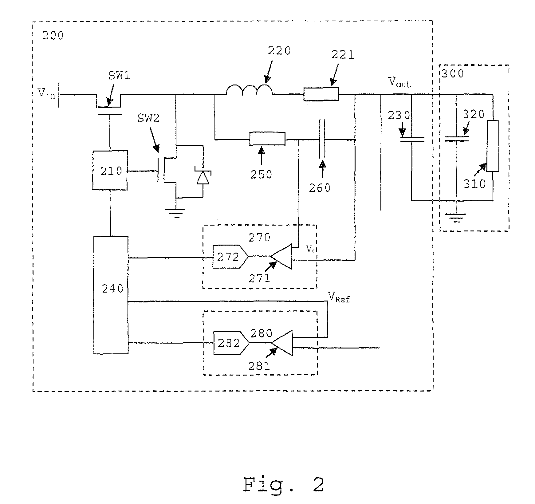
[0025]FIG. 2 is a schematic of a switched mode DC / DC power supply 200 according to an embodiment of the present invention connected to a load 300. The load 300 comprises a resistive load represented by a resistor 310 of resistance Rload, and a capacitive element represented by a capacitor 320 of capacitance Cload. The resistive load and the capacitive element are connected in parallel between an output of the SMPS and a terminal held at a reference potential such as earth. The capacitive element may be a capacitor or any other electrical circuit component having a capacitance, for example a portion of a signal line electrostatically coupled to a grounded conductor. The capacitive element may be directly connected to the SMPS output and / or reference potential, or indirectly connected to the SMPS output and / or reference potential via one or more other capacitive elements or other electrical circuit components.

[0026]The power supply includes transistors SW1 and SW2 which are preferably...


PUM


Abstract

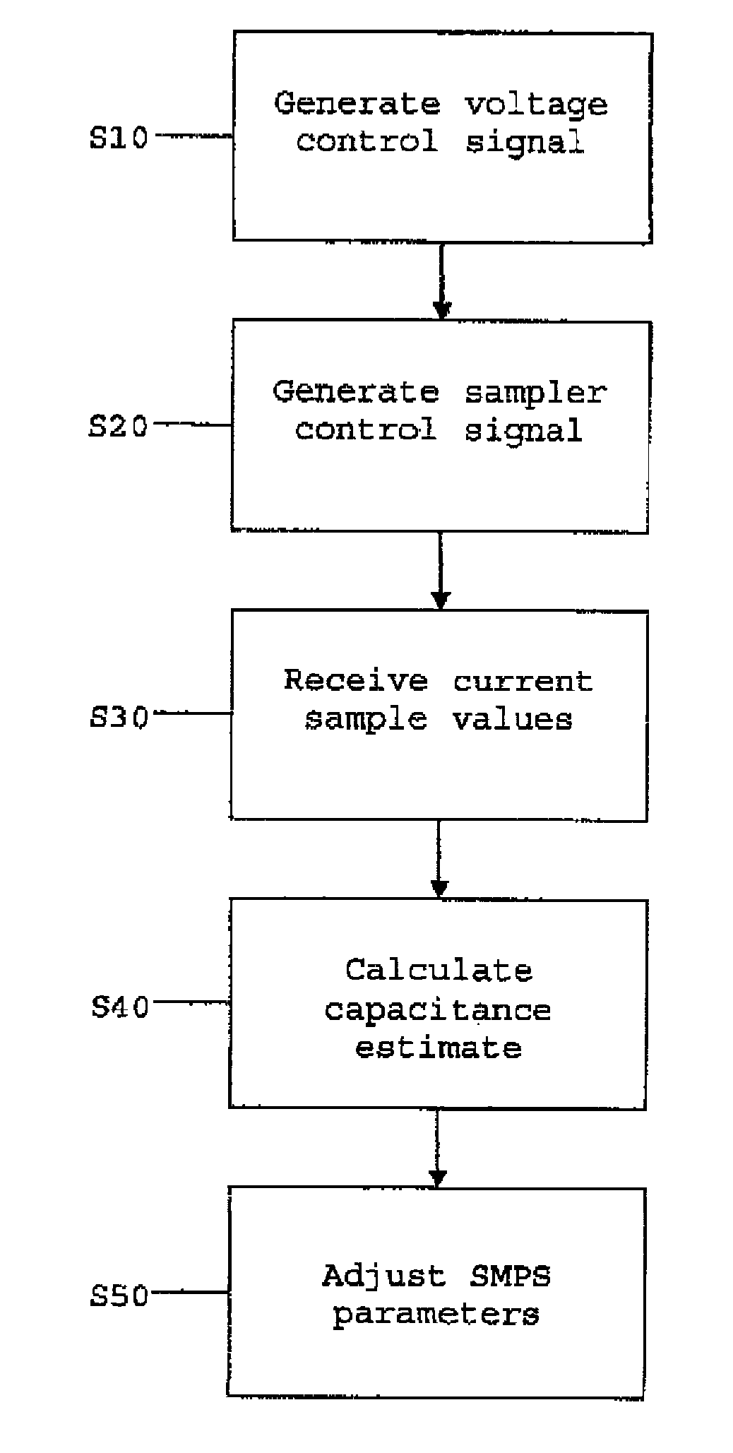
A method of determining a measure of a total capacitance of one or more capacitive elements connected to an output of a switched mode power supply is described. The method includes generating a voltage control signal to cause an output voltage controller to sweep a voltage at the output of the switched mode power supply from an initial voltage value to a final voltage value. Sample values of a current at the output measured by a current sampler during the sweep of the output voltage are received, and an integrated current value representing a measure of the total capacitance using the received sample values is calculated.

Description

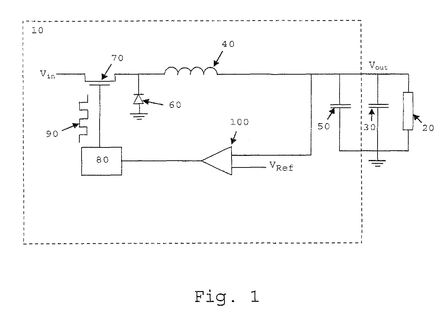
[0001]This application claims the benefit of U.S. Provisional Application No. 61 / 220,334, filed Jun. 25, 2009, the disclosure of which is fully incorporated herein by reference.TECHNICAL FIELD[0002]The present invention generally relates to the field of switched mode power supplies (sometimes referred to as switch mode power supplies or switching mode power supplies) and more specifically to the determination of a measure of the total capacitance of one or more capacitive elements connected to an output of a switched mode power supply.BACKGROUND[0003]The switched mode power supply (SMPS) is a well-known type of power converter having a diverse range of applications by virtue of its small size and weight and high efficiency, for example in personal computers and portable electronic devices such as cell phones. An SMPS achieves these advantages by switching a switching element such as a power MOSFET at a high frequency (usually tens to hundreds of kHz), with the frequency or duty cycl...

Claims


Application Information

Patent Timeline
Patent Type & Authority Patents(United States)
IPC IPC(8): G05F1/00G01R27/26H02M3/157
CPCH02M3/157G01R27/2605
Inventor KARLSSON, MAGNUSHOLMBERG, TORBJORNLENELLS, MATZ
Owner FLEX LTD
Learn More