Transfer bar

a transfer bar and bending moment technology, applied in the field of transfer bars, can solve the problems of low rigidity against loads imposed and inability to resist bending moments, and achieve the effects of increasing the rigidity of the connecting part, reliably resisting bending moments, and increasing the speed at which the transfer bar is driven

Active Publication Date: 2014-10-14
KOMATSU LTD +2
View PDF26 Cites 6 Cited by
  • Summary
  • Abstract
  • Description
  • Claims
  • Application Information

AI Technical Summary

Benefits of technology

[0016]In the first aspect of the invention, the male and female fitted portions on the remaining-side clamp and the movable-side clamp of the connecting device that define the first connector include a predetermined inner area that accommodates the male and female engagement portions and a large fitted surface around the connecting direction that enables fitting between the male fitted portion and the female fitted portion, thus significantly increasing rigidity of a connecting part between the remaining bar and movable bar when the connecting device is used. Hence, the connecting device reliably resists a bending moment generated on the connecting part even when large loads are applied onto the connecting part in a direction orthogonal to the connecting direction, so that a speed at which the transfer bar is driven can be increased.
[0018]In the second aspect of the invention, an ability of the movable member to roll and move facilitates the movement of the movable member and expedites the engagement of the male and female engagement portions on the second connector, while causing less abrasion and simplifying lubrication, thus facilitating maintenance of the connecting device.
[0018]In the second aspect of the invention, an ability of the movable member to roll and move facilitates the movement of the movable member and expedites the engagement of the male and female engagement portions on the second connector, while causing less abrasion and simplifying lubrication, thus facilitating maintenance of the connecting device.
[0019]In the third aspect of the invention, the movable member that includes a plurality of movable members arranged around the connecting direction effects the engagement of the male and female engagement portions in a well-balanced manner, keeping the engagement in good conditions.
[0020]In the fourth aspect of the invention, an advancement of the plunger, by which the movable member is moved on a slant surface provided on the plunger, changes a direction in which the plunger is moved in the connecting direction to the direction orthogonal to the connecting direction, thus ensuring a movement of the movable member toward the male engagement portion.
[0021]In the fifth aspect of the invention, the slant surface presses the movable member toward the male engagement portion, keeping the movable member from shaky movement while the male and female engagement portions are engaged, so that a connection between the bars is kept in better conditions.
[0022]In the sixth aspect of the invention, the male and female fitted portions that have a truncated conic shape are fitted with each other. Thus the fitted surfaces of the male and female fitted portions can be closely contacted, resulting in an increased rigidity and reliable resistance against a greater bending moment.

Problems solved by technology

However, a connecting mechanism disclosed in Patent Literatures 1 and 2, in which dampers and the plate-shaped engagement members provided on the remaining bars make vertical and pivotal movement, has low rigidity against loads imposed in a horizontal direction because the dampers and the engagement members are vertically engaged or disengaged from an engaged part on the movable bar, although the mechanism is sufficiently resistant against loads vertically applied by either the self weight of the transfer bar or an acceleration of speed at which the transfer bar is vertically moved.
Accordingly, an attempt to drive the transfer bar faster to increase productivity of the press machine turns horizontally-imposed loads on connectors of each of the bars into significant bending moment, in addition to creating vertically-applied loads on the connectors, thus being unable to resist the bending moment.

Method used


Image

  • Transfer bar
  • Transfer bar
  • Transfer bar

Examples


first exemplary embodiment

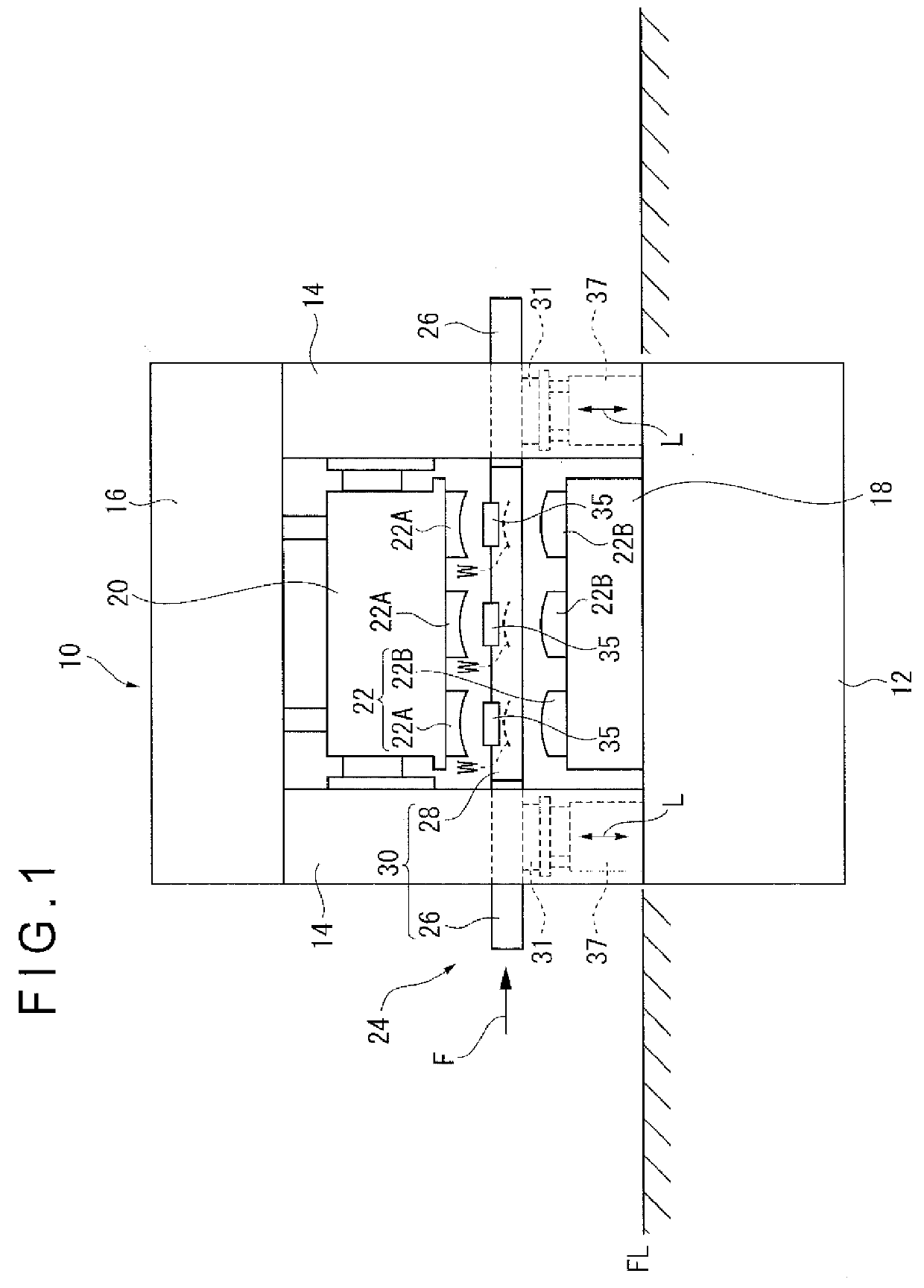
[0033]The following is a detailed description of a first exemplary embodiment of the invention with reference to drawings. FIG. 1 shows a transfer press 10 (a press machine) in a front view. The transfer press 10 has a bed 12 installed under a floor FL, the bed 12 having a rectangular shape in a plan view. Columnar uprights 14 are vertically mounted at the four corners of the bed 12 in a plan view. A crown 16 is supported on the four uprights. The crown 16 has a slide 20 vertically mounted, enabling vertical movements of the slide 20 by an appropriate driving mechanism within the crown 16. These components constitute a press body of the transfer press 10.

[0034]A moving bolster 18 is disposed on the bed 12. The moving bolster 18 is configured such that the moving bolster 18 can be smoothly transferred from the press body to the exterior or moved back inside using appropriate guiding member including a rail. Detachable lower die 22B, one of dies 22 for processing workpiece, is mounted...

second exemplary embodiment

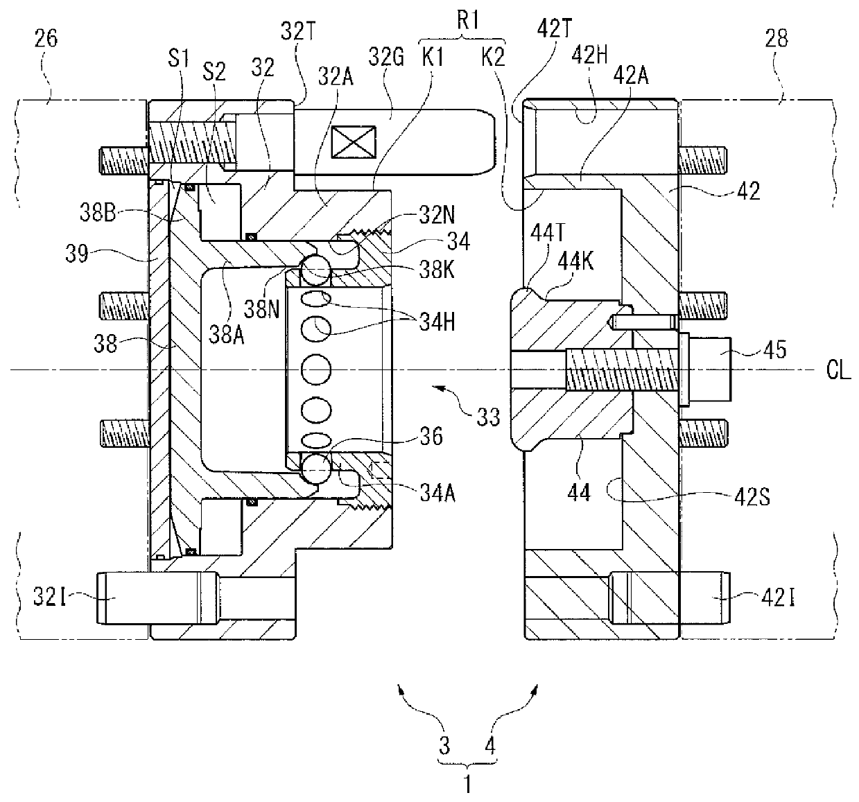
[0060]FIG. 6 shows a second exemplary embodiment of the invention. Whereas the male fitted portion K1 and the female fitted portion K2 on the first connector R1 are disposed on a surface parallel to the central axis CL in the first exemplary embodiment, the two portions are provided by a truncated conical surface in the second exemplary embodiment. In other words, the male fitted portion K1 is provided by a tapered surface on an outer circumference of a truncated cone tapering toward an end in a fitting direction (the same as the connecting direction), while the female fitted portion K2 is provided by a tapered surface on an inner circumference of a truncated cone of which diameter increases toward an end of the fitting direction.

[0061]The second exemplary embodiment offers an advantage of increasing rigidity in a connection between the bars 26 and 28 by ensuring contact between the fitted portions K1 and K2 to the entire circumference.

third exemplary embodiment

[0062]FIG. 7 shows a third exemplary embodiment of the invention. Whereas the first exemplary embodiment uses the sphere 36 (a moveable member according to the invention), the exemplary embodiment employs a roller 51 that has a cylindrical shape with a predetermined length. The retainer 34 is provided with a square shell-shaped inner square hollow portion 34C in lieu of the inner cylindrical portion 34A discussed in the first exemplary embodiment. Each of members of the inner square hollow portion 34C is provided with the penetrating hole 34H (a square opening), each accommodating the roller 51.

[0063]On the other hand, the end of the intermediate cylindrical portion 38A on the plunger 38 defines an intermediate square hollow portion 38C. An inner circumference of the outer cylindrical portion 32A on the remaining-side outer component 32 is defined by a multi-level surface created by a circular opening in contact with an outer circumference of the intermediate cylindrical portion 38A...


PUM

PropertyMeasurementUnit
circumferenceaaaaaaaaaa
shapeaaaaaaaaaa
outer circumferenceaaaaaaaaaa

Abstract

A connecting device connecting a remaining bar and a movable bar of a transfer bar includes a remaining-side clamp and a movable-side clamp. The clamps respectively have a male fitted portion and a female fitted portion that are fitted to one another around a connecting direction, defining a first connector. A male engagement portion and a female engagement portion are provided inside the clamps, defining a second connector. The female engagement portion of the second connector includes a sphere in a form of a movable member moving in a direction orthogonal to the connecting direction. A movement of the sphere effects an engagement and disengagement of the female engagement portion from the male engagement portion.

Description

TECHNICAL FIELD[0001]The invention relates to a transfer bar, more specifically a connecting mechanism for a transfer bar installed on a workpiece transfer device of a press machineBACKGROUND ART[0002]A transfer press, i.e. a press machine installed with a plurality of processing stations within its press body, is provided with a workpiece transfer device that transfers workpieces in sequence among the processing stations. The workpiece transfer device includes a pair of transfer bars mounted in parallel with a direction in which workpieces are transferred, each of the transfer bars being provided with detachable workpiece holders capable of holding and releasing workpieces depending on a position and a type of dies disposed in respective processing stations.[0003]The dies need to be replaced according to a type of the workpiece (type of product). A lower die, the die normally installed on a moving bolster, is transferred from the press body to the exterior together with the moving ...

Claims


Application Information

Patent Timeline
Patent Type & Authority Patents(United States)
IPC IPC(8): B21D43/05
CPCB21D43/055B21D43/057
Inventor NISHIDA, KENJIMORIYASU, TAKASHIAKASHI, HIDETOSHIKOBAYASHI, TOMOYA
Owner KOMATSU LTD
Why Eureka
Try Eureka