Method and device for detecting particulate matter contained in a gas to be measured

a technology of particulate matter and gas, which is applied in the direction of variable capacitors, instruments, machines/engines, etc., can solve the problems of detecting damage and deterioration of electrodes, clogging of dpf, and increasing pressure loss, so as to achieve accurate measurement, increase the direct current resistance between parallel plate conductors, and detect stably

Active Publication Date: 2014-10-14
DENSO CORP
View PDF12 Cites 26 Cited by
  • Summary
  • Abstract
  • Description
  • Claims
  • Application Information

AI Technical Summary

Benefits of technology

[0019]The present invention has been achieved in light of the above-described issues. An object of the present invention is to provide an electrical-resistance-type particulate matter detecting device used to detect particulate matter within exhaust gas of an internal combustion engine. The particulate matter detecting device is highly reliable, having high detection accuracy and being capable of detecting disconnection abnormality. The present invention also provides a method of manufacturing a particulate matter detection element used in the particulate matter detecting device. The present invention also provides a method of detecting disconnection in a particulate matter detecting device.
[0026]As a result of the direct-current detector detecting the direct current flowing to the particulate matter detection element, detection resistance formed by the particulate matter accumulated between the detection electrodes can be accurately measured.
[0027]At this time, as a result of an insulating ceramic being used as the dielectric layer, the direct current resistance between the parallel plate conductors can be increased and insulation properties can be ensured in the capacitance component. Therefore, the amount of particulate matter accumulated in the detection section can be stably detected without the direct current flowing to the capacitance component and without the output of the detected resistance detected by the direct-current detector being affected.

Problems solved by technology

When the amount of collected PM exceeds an allowable amount, the DPF becomes clogged.
Pressure loss may increase.
As a result of the resistance layer being formed, damage and deterioration of the electrodes can be detected.
However, in a conventional electrical-resistance-type particulate matter detecting device, such as that described in JP-A-S59-197847, when the particulate matter accumulated between detection electrodes is heated and removed, the resistance between the detection electrodes becomes extremely high, causing an almost insulated state.
Therefore, it may be difficult to use the value of the detected resistance to differentiate between a state in which particulate matter is not accumulated between the detection electrodes, and a state in which a disconnection abnormality has occurred in an electrical wire of a signal line connecting a detection element and a detection circuit or the like.
As a result, malfunction may occur.
Furthermore, the resistance value of the conductive layer is required to be adjusted with high accuracy, leading to increase in manufacturing cost.
Moreover, the metal configuring the detection electrodes inevitably becomes dispersed in the conductive layer as a result of extended use.
The resistance value of the conductive layer changes, thereby causing instable output.

Method used


Image

  • Method and device for detecting particulate matter contained in a gas to be measured
  • Method and device for detecting particulate matter contained in a gas to be measured
  • Method and device for detecting particulate matter contained in a gas to be measured

Examples


first embodiment

[0051]A first embodiment will be described with reference to FIG. 1 to FIGS. 9A and 9B, and FIG. 13.

[0052]A particulate matter detecting device 100 according to the first embodiment of the present embodiment is provided on an exhaust gas flow path of an internal combustion engine. The exhaust gas serves as the gas to be measured. The particulate matter detecting device 100 detects the amount of particulate matter within the gas to be measured. Combustion control of the internal combustion engine, regeneration of an exhaust emission control device, abnormality diagnosis, and the like are performed using the detection result.

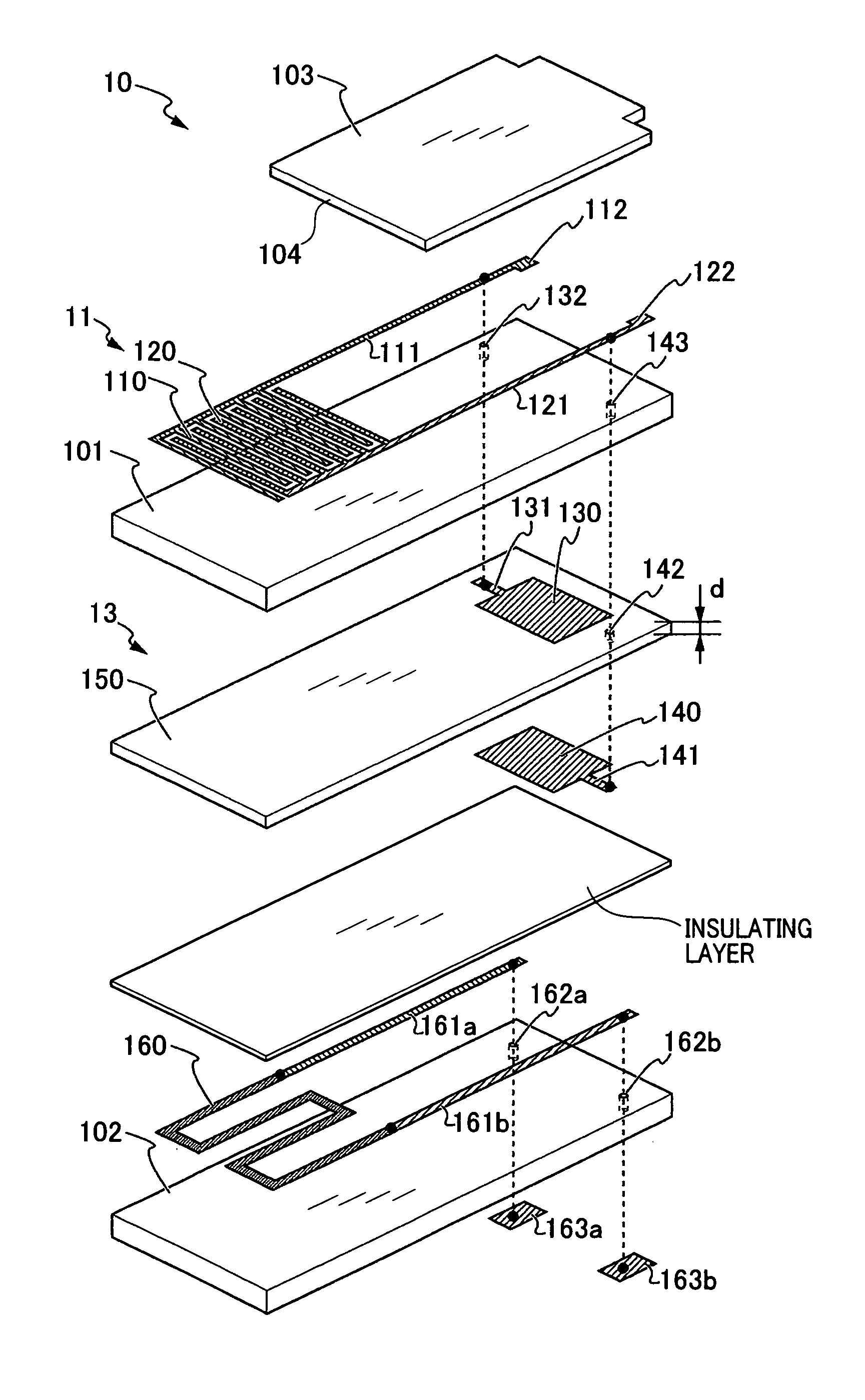
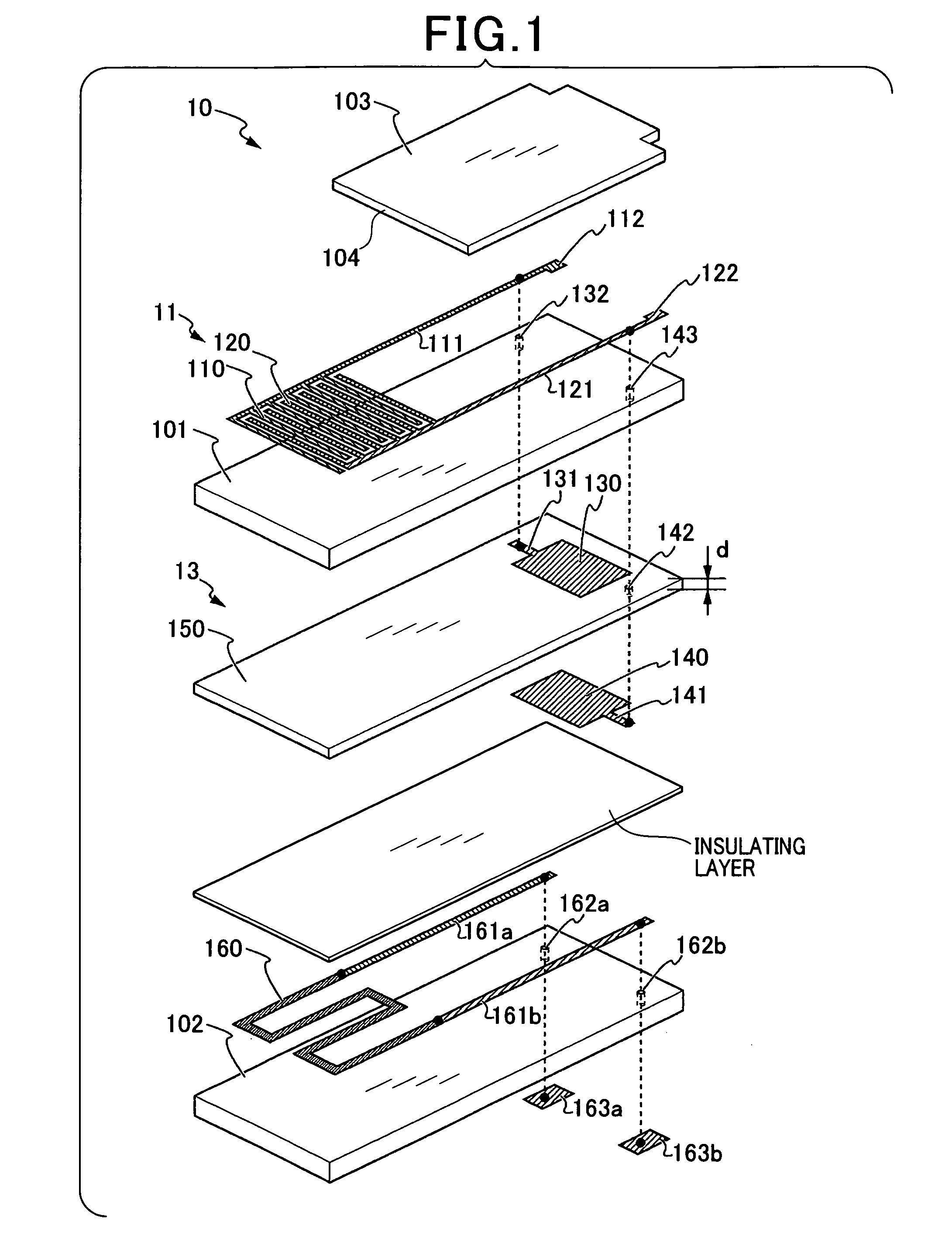
[0053]The particulate matter detecting device 100 includes at least a particulate matter detection element 10 and a detection circuit 20. The particulate matter detection element 10 is provided with a pair of detection electrodes 110 and 120 serving as a detection section 11. The pair of detection electrodes 110 and 120 are provided such as to oppose each other wi...

second embodiment

[0128]A particulate matter detection element 10a according to a second embodiment of the present embodiment will be described with reference to FIG. 10. In the second embodiment and subsequent embodiments, configurations similar to those according to the first embodiment are given the same reference numbers. Explanations thereof are omitted.

[0129]According to the first embodiment, an example is described in which the dielectric layer 150 is formed in a rough plate shape by the doctor blade method or the like. The dielectric layer 150 is layered on the rear-surface side of the insulating substrate 101 configuring the detection section 11. As an alternative, as described according to the second embodiment, a capacitance element may be formed on the front-surface side of the insulating substrate 101 on which the detection electrodes 110 and 120 are provided. Specifically, a first plate conductor 130a and a first conductor lead section 121a may be formed on the front surface of the insu...

third embodiment

[0132]A particulate matter detection element 10b according to a third embodiment of the present embodiment will be described with reference to FIG. 11 and FIG. 12.

[0133]According to the first and second embodiments, a configuration is described in which the detection section 11 is a plurality of detection electrodes 110 and 120 opposing each other such as to be arrayed in a comb-shape. As an alternative, as described according to the third embodiment, detection electrodes 110b and 120b that extend linearly may be disposed opposing each other as opposing electrodes. The detection electrodes 110b and 120b may be covered by an insulating protective layer 103b provided with an opening section 104 such that the detection section 11b is exposed.

[0134]According to the third embodiment as well, in a state in which the particulate matter is accumulated between the detection electrodes 110b and 120b, a capacitance component 13b is connected in parallel to the detected resistance RSEN. In a st...


PUM

PropertyMeasurementUnit
temperatureaaaaaaaaaa
direct current resistanceaaaaaaaaaa
alternating current impedanceaaaaaaaaaa

Abstract

A particulate matter detection element includes a capacitance component disposed in parallel with a detected resistance RSEN. A direct current-power source that supplies a direct current (IDC) for particulate matter detection, and an alternating-current power source that supplies an alternating current (IAC) for disconnection detection are provided.

Description

CROSS REFERENCE TO RELATED APPLICATION[0001]This application is based upon and claims the benefit of priority from the prior Japanese Patent Application No. 2010-242162, filed Oct. 28, 2010, the entire contents of which is incorporated herein by reference.BACKGROUND OF THE INVENTION[0002]1. Field of the Invention[0003]The present invention relates to a method and device for detecting an amount of particulate matter contained in a gas to be measured, such as an exhaust gas from vehicles, and in particular, the method and apparatus detect an amount of the particulate matter based on electrical resistance caused by the particulate matter accumulating between electrodes. The present invention also relates to a method of manufacturing a particulate matter detection element used in the particulate matter detecting device.[0004]2. Description of the Related Art[0005]The exhaust gas of a diesel engine of an automobile and the like may include environmental pollutants, particularly particula...

Claims


Application Information

Patent Timeline
Patent Type & Authority Patents(United States)
IPC IPC(8): G01R27/26G01N15/06F01N11/00G01N27/62F01N9/00
CPCG01N15/0656Y02T10/47F01N9/002F01N2550/04F01N2560/05F01N11/00Y02T10/40Y10T29/435
Inventor KIMATA, TAKEHITOMATSUOKA, MIKIYASU
Owner DENSO CORP
Why Eureka
Try Eureka