Surveillance system comprising a radar antenna mounted on a blade of a windmill

a technology of radar antenna and windmill blade, which is applied in the direction of machines/engines, using reradiation, instruments, etc., can solve the problems of difficult to fly a true stationary helicopter difficult to fly a true circle at a constant altitude and speed, and low cross-range resolution of existing surveillance systems. achieve the effect of enhancing the cross-range between targets, improving target classification, and easy building a permanent and very large-area surveillance system

Active Publication Date: 2014-10-14
THALES NEDERLAND BV
View PDF15 Cites 6 Cited by
  • Summary
  • Abstract
  • Description
  • Claims
  • Application Information

AI Technical Summary

Benefits of technology

[0013]Thus, an advantage provided by the present invention is that it makes it possible to easily build a permanent and very large area surveillance system, based on the number of existing windmill farms. The observed area can expand at the same high rate as the number of windmill farms. Moreover, the swath is vertical,

Problems solved by technology

While the existing techniques focus on accurately determining range, i.e. the distance of the detected objects relatively to the radar, it is a remaining issue to better estimate the distance between the detected objects, so-called “cross-range”.
Indeed, the existing surveillance systems provide quite a low cross-range resolution.
A major drawback is that it is difficult to fly a helicopter a

Method used


Image

  • Surveillance system comprising a radar antenna mounted on a blade of a windmill
  • Surveillance system comprising a radar antenna mounted on a blade of a windmill
  • Surveillance system comprising a radar antenna mounted on a blade of a windmill

Examples


Embodiment Construction

[0017]In the figures, like reference signs are assigned to like items.

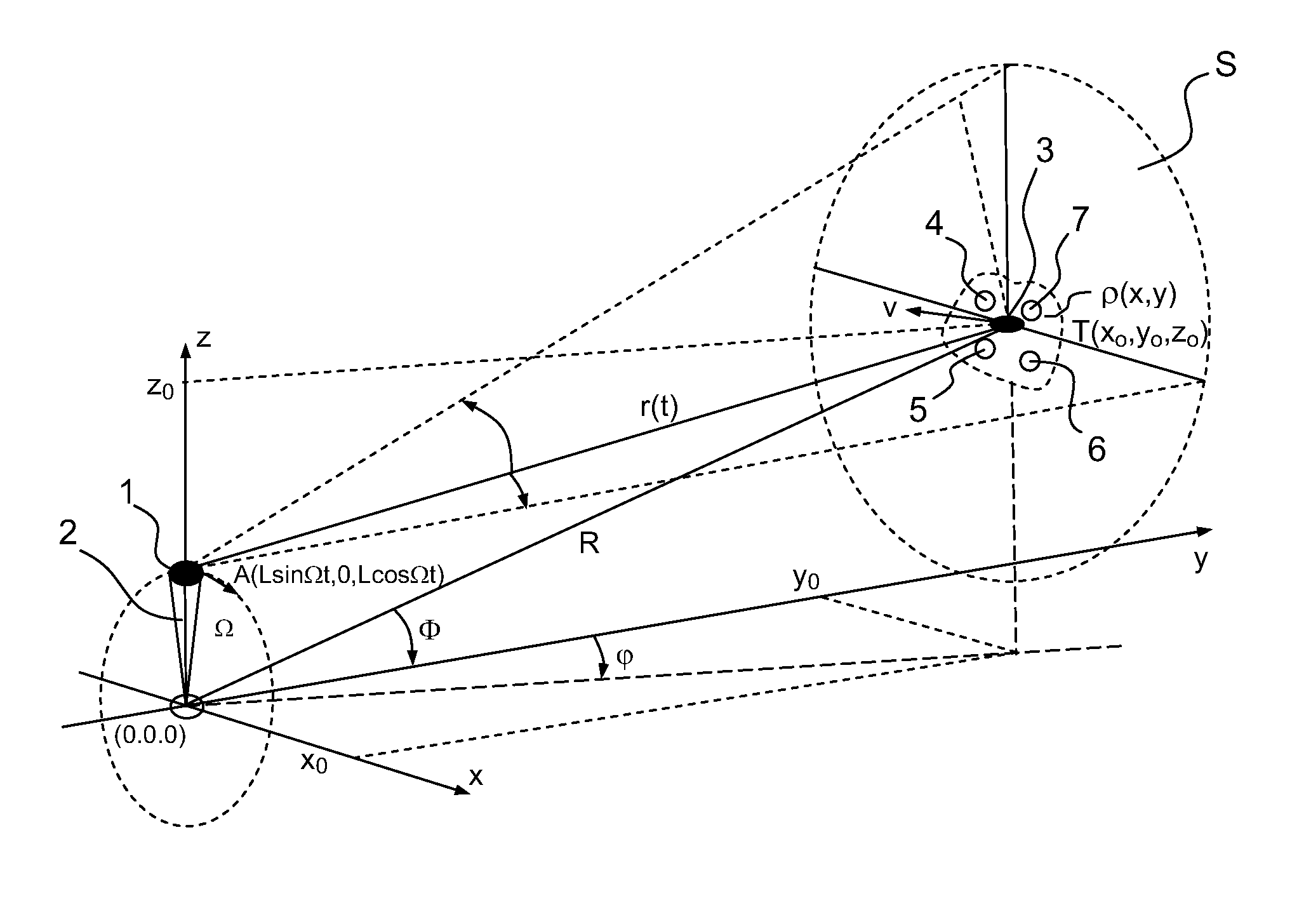
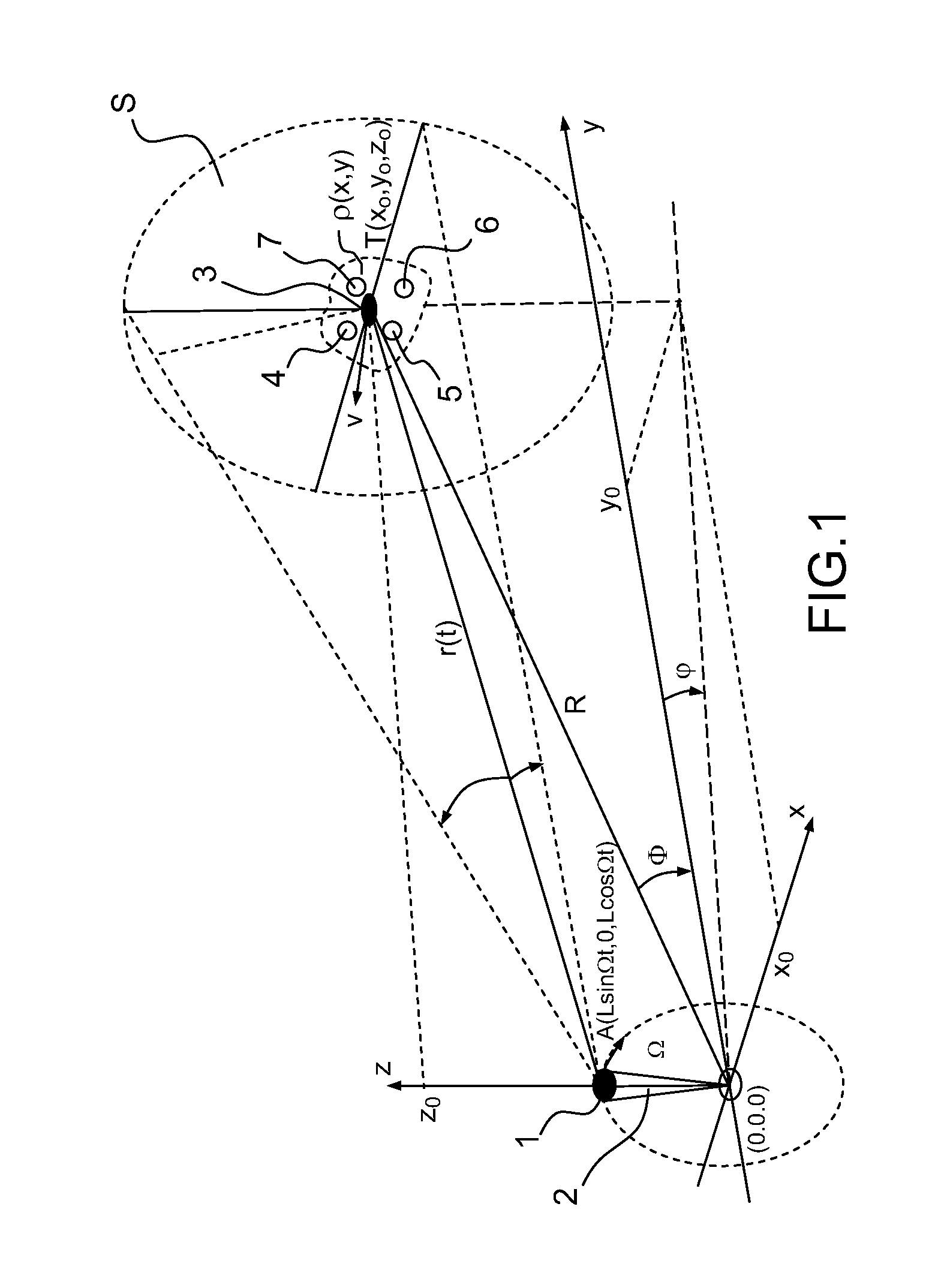
[0018]The FIG. 1 schematically illustrates the geometry of an examplary windmill-SAR according to the invention. The knowledge of the relative target-antenna motion is essential in the SAR techniques. However, it can be a priori unknown or poorly determined especially with non-cooperating targets. In such a radar system according to the invention, the antenna motion is known and can be used to improve the resolution, especially in azimuth and elevation. Thus, the SAR technique can improve the cross-range resolution because the received signal reveals both azimuth and elevation cross-ranges.

[0019]In this first embodiment, a single antenna 1 may be mounted on a single blade 2 of a windmill. L being the length of the blade and the rotation axis of the windmill blades being at (0,0,0), the antenna 1 rotates with a radial speed Ω in a vertical x-z plane from (0,0,L) to (L sin Ωt,0,L cos Ωt) at time t. A target 3 transl...


PUM


Abstract

A surveillance system for detecting targets comprises a radar antenna mounted on a blade of a windmill.

Description

CROSS-REFERENCE TO RELATED APPLICATIONS[0001]This application is a National Stage of International patent application PCT / EP2009 / 065999, filed on Nov. 27, 2009, which claims priority to foreign European patent application No. EP 08170468.6, filed on Dec. 2, 2008, the disclosures of which are incorporated by reference in their entirety.FIELD OF THE INVENTION[0002]The present invention relates to a surveillance system comprising a radar antenna mounted on a blade of a windmill. The invention is more particularly applicable to the domain of surveillance.BACKGROUND[0003]Some systems ensure surveillance of large air / sea / ground areas in the purpose of detecting objects such as aircrafts, vessels or vehicles, whether they are moving or not. They may basically consist of a network of radar systems. While the existing techniques focus on accurately determining range, i.e. the distance of the detected objects relatively to the radar, it is a remaining issue to better estimate the distance bet...

Claims


Application Information

Patent Timeline
IPC IPC(8): G01S13/88F03D11/00G01S13/04G01S13/90G01S13/91
CPCF03D11/00G01S13/04G01S13/9035G01S2013/9082F05B2260/80G01S13/91Y02E10/722G01S13/34F03D17/00G01S13/9088G01S13/904G01S13/90Y02E10/72G01S13/9082
Inventor HOL, WILLEM ANDRIESPEERDEMAN, TONERKOCEVIC-PRIBIC, RADMILA
Owner THALES NEDERLAND BV
Why Eureka
Try Eureka