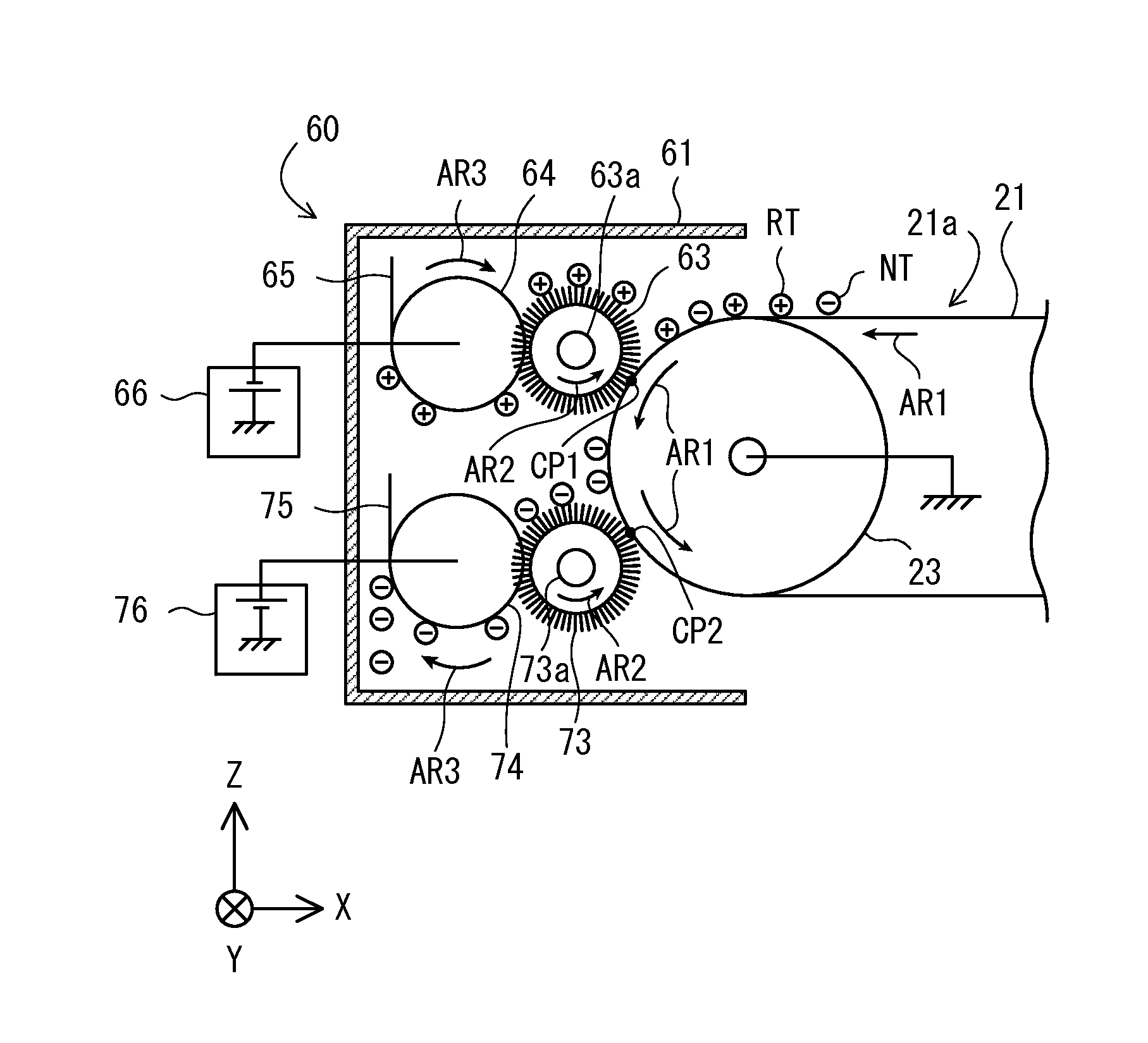
Image forming apparatus
a technology of forming apparatus and forming roller, which is applied in the direction of electrographic process apparatus, instruments, optics, etc., can solve the problem that the toner cannot be uniformly removed by the brush roller, and achieve the effect of efficient removal
- Summary
- Abstract
- Description
- Claims
- Application Information
AI Technical Summary
Benefits of technology
Problems solved by technology
Method used
Image
Examples
first embodiment
1. First Embodiment
1.1. Configuration of Image Forming Apparatus
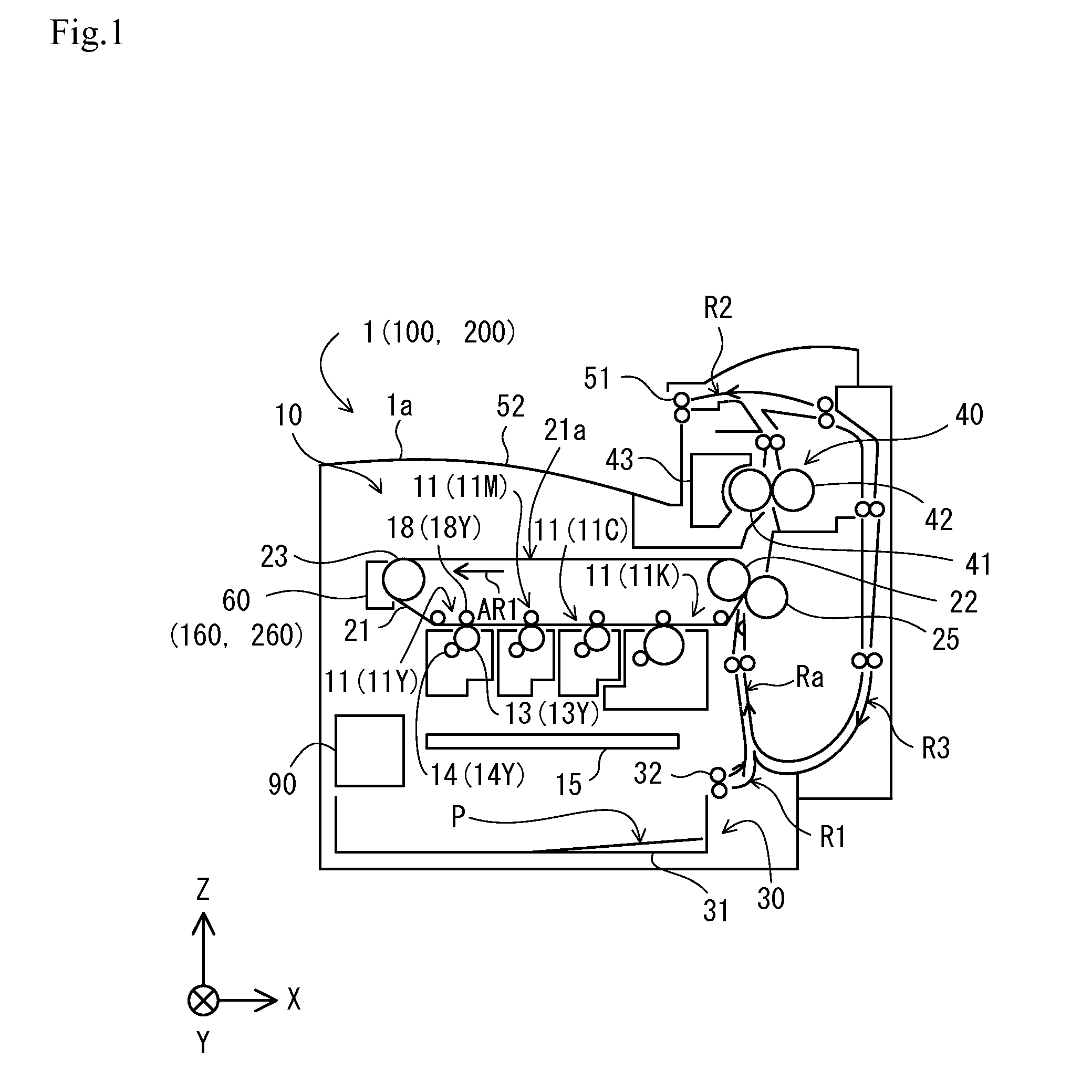
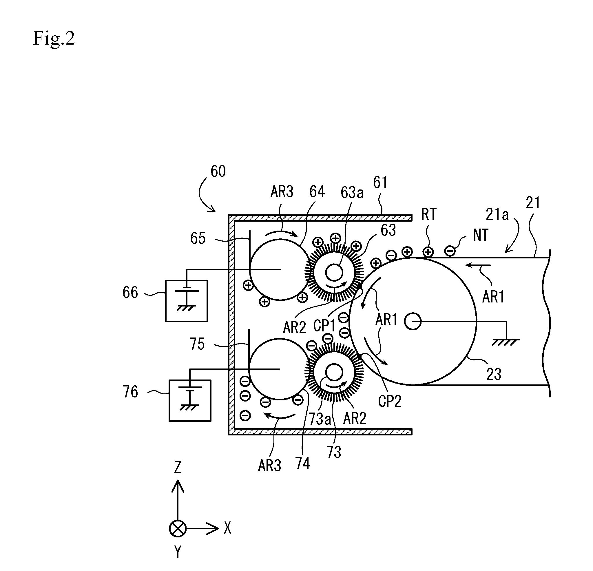
[0038]FIG. 1 is a front view showing an example of an overall configuration of an image forming apparatus 1 of an embodiment of the present invention. The image forming apparatus 1 is used as, for example, a multi-function machine integrally incorporating copy, printing, and fax capabilities, and prints a monochrome image or a color image by electrophotography. As shown in FIG. 1, the image forming apparatus 1 mainly includes a printer unit 10, a sheet feeder 30, a fixing unit 40, a discharge unit 50, and a cleaning unit 60.
[0039]FIG. 1 and subsequent drawings are provided, as appropriate, with an XYZ orthogonal coordinate system in which a Z axis direction is a vertical direction and an XY plane is a horizontal plane, to clarify the directional relationship in the drawings. Arrows provided to a sheet feed path R1, a discharge path R2, a circulation path R3, and a conveyance path Ra in FIG. 1 show “conveyance direction ...
second embodiment
2. Second Embodiment
[0095]A second embodiment of the present invention will be described below. An image forming apparatus 100 of the second embodiment has the same hardware configuration as the image forming apparatus 1 of the first embodiment, except that a plurality of lubricant suppliers 168 and 178 are provided. Thus, the difference is mainly described below.
[0096]Components common in the image forming apparatuses 1 and 100 are denoted with the same reference numerals. The components given the same reference numerals are described in the first embodiment and thus will not be described in this embodiment.
2.1. Configuration of Cleaning Unit
[0097]FIG. 7 is a front view of showing an example of a configuration of a cleaning unit 160 of the second embodiment. Like the cleaning unit 60 of the first embodiment, the cleaning unit 160 removes the remaining toner on the intermediate transfer belt 21 after the toner image is transferred onto the recording medium P from the intermediate tr...
third embodiment
3. Third Embodiment
[0108]Next, a third embodiment of the present invention will be described below. An image forming apparatus 200 of the third embodiment has the same hardware configuration as the image forming apparatus 100 of the second embodiment, except that a removing blade 279 is provided. Thus, the difference is mainly described below.
[0109]Components common in the image forming apparatuses 100 and 200 are denoted with the same reference numerals. The components given the same reference numerals are described in the second embodiment and thus will not be described in this embodiment.
[0110]FIG. 8 is a front view of showing an example of a configuration of a cleaning unit 260 of the third embodiment. Like the cleaning unit 160 of the second embodiment, the cleaning unit 260 removes the remaining toner on the intermediate transfer belt 21 after the toner image is transferred onto the recording medium P from the intermediate transfer belt 21. As shown in FIG. 8, the cleaning uni...
PUM
 Abstract
Description
Claims
Application Information
 - R&D
- Intellectual Property
- Life Sciences
- Materials
- Tech Scout
- Unparalleled Data Quality
- Higher Quality Content
- 60% Fewer Hallucinations
Browse by: Latest US Patents, China's latest patents, Technical Efficacy Thesaurus, Application Domain, Technology Topic, Popular Technical Reports.
© 2025 PatSnap. All rights reserved.Legal|Privacy policy|Modern Slavery Act Transparency Statement|Sitemap|About US| Contact US: help@patsnap.com


