Method for the remediation of contaminated soil

a technology for contaminated soil and remediation methods, applied in the direction of combustion process, protective foundation, lighting and heating apparatus, etc., can solve the problems of leaking liquid, affecting the quality of soil,

Active Publication Date: 2014-10-21
KUNZ DALE
View PDF4 Cites 8 Cited by
  • Summary
  • Abstract
  • Description
  • Claims
  • Application Information

AI Technical Summary

Benefits of technology

[0014]By providing the processing cell in this way, the following advantages are achieved:
[0016]the cell is located immediately adjacent the feedstock, thereby minimizing transportation cost.
[0019]optionally, a cover or tarp may be spread over the filled chamber, to minimize the escape of solvent vapor;

Problems solved by technology

In the Gulf War, oil wells were opened and set on fire.
While the oil was initially of low viscosity, its light ends have evaporated over time and the remaining viscous residue is now immobile.
As a consequence, shallow surface layers of sand have been left, contaminated with oil and salt.
The land involved has since been barren and useless.
Vegetation has difficulty growing on it and the salt is toxic for animals.
However, it is contemplated that the technique involved may be applied in other circumstances where a porous, permeable surface layer of soil has been contaminated with hydrocarbons, chemicals and the like.

Method used


Image

  • Method for the remediation of contaminated soil
  • Method for the remediation of contaminated soil
  • Method for the remediation of contaminated soil

Examples


Embodiment Construction

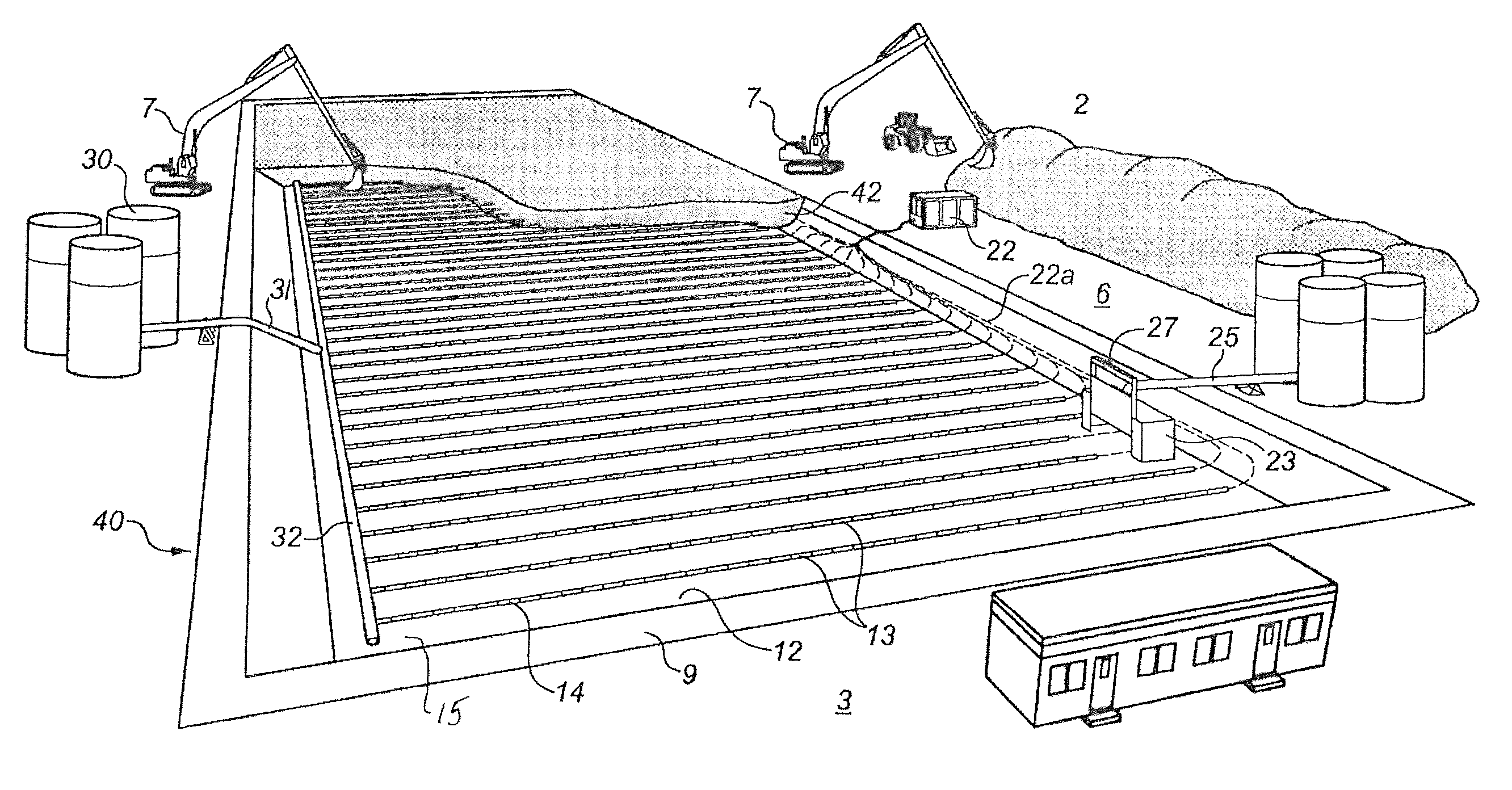
[0040]The method will be described in connection with remediating a surface layer 1 of oil-contaminated sand 2, such as exists in Kuwait. The sand 2 is unconsolidated, porous and permeable. It typically comprises 34 wt. % oil, 64 wt. % sand and 1 or 2 wt. % salt. The contamination commonly extends down from ground surface 3 to a depth of about 10 feet.

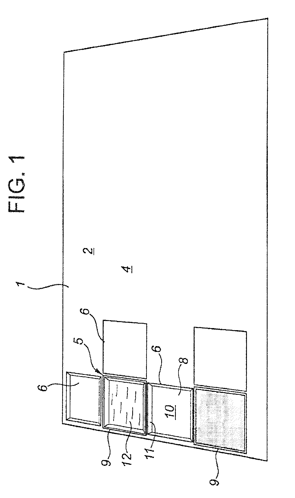
[0041]As shown in FIG. 1, a tract 4 is sub-divided into a central area 5 and surrounding adjacent areas 6. The areas 5, 6 may be rectangular in configuration and substantially contiguous. For instance, each area may be about 200 meters in length and 50 meters in width.

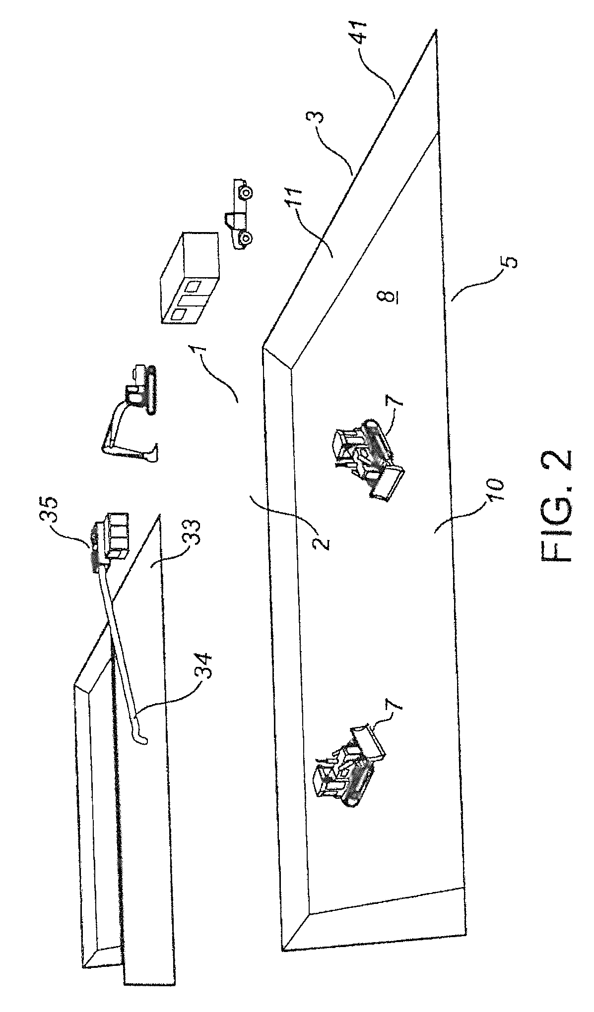
[0042]The width may be selected so that excavators 7 (see FIG. 3), positioned on each side edge of a pit area, can extend their buckets to about the centerline of the pit to be excavated.

[0043]As shown in FIG. 2, in a first step of the process, machines 7, such as excavators, bulldozers, loaders and trucks, are used to excavate the oil-contaminated sand 2 from the central...


PUM


Abstract

A containment chamber is constructed by excavating a pit at the site of oil-contaminated sand and lining the pit with an impermeable, heat-resistant, flexible plastic liner. An array of spaced apart heating assemblies is positioned to cover the bottom of the chamber. Each heating assembly may include an elongate linear electric resistance heater positioned within a tubular slotted sand screen. The containment chamber is filled with a charge of contaminated sand. Solvent, such as diesel fuel, is pumped into the elongate passageways defined between the heaters and screens. The heaters are actuated to vaporize the solvent, which moves through the screen slots and convectively permeates the charge. The vapor transfers heat to the oily sand and condenses. Condensed solvent and heated oil drain and are recovered from the chamber.

Description

CROSS-REFERENCE TO RELATED APPLICATIONS[0001]This application claims priority from U.S. Provisional Application Ser. No. 61 / 431,744, entitled “METHOD FOR THE REMEDIATION OF OIL CONTAMINATED SOIL”, filed Jan. 11, 2011, the entirety of which is hereby incorporated by reference.FIELD OF THE INVENTION[0002]The present invention relates to a method for remediating a surface layer of contaminated soil and providing a processing cell in which to carry out the method.BACKGROUND[0003]In the Gulf War, oil wells were opened and set on fire. Large areas of surrounding sand were covered with unburned crude oil. Salt water was used to assist in extinguishing the fires—it too covered large areas of the surrounding sand. Some of the oil and salt water penetrated downwardly into the porous, permeable, unconsolidated sand to a shallow depth (for example, to a depth of 10 feet). Much of the water evaporated, but the salt remained.[0004]While the oil was initially of low viscosity, its light ends have ...

Claims


Application Information

Patent Timeline
Patent Type & Authority Patents(United States)
IPC IPC(8): B09C1/06B09C1/02
CPCB09C1/025B09C1/062
Inventor KUNZ, DALE
Owner KUNZ DALE
Why Eureka
Try Eureka