
Disposal of electrical and electronic equipment

a technology applied in the field of disposal of electrical and electronic equipment, can solve the problems of non-volatile residues resulting from the method, and achieve the effects of simple and efficient processing of equipment, enhanced efficiency, efficiency and safety, and simple and efficient processing

Active Publication Date: 2014-10-21
P FUEL
View PDF39 Cites 5 Cited by
  • Summary
  • Abstract
  • Description
  • Claims
  • Application Information

AI Technical Summary

Benefits of technology

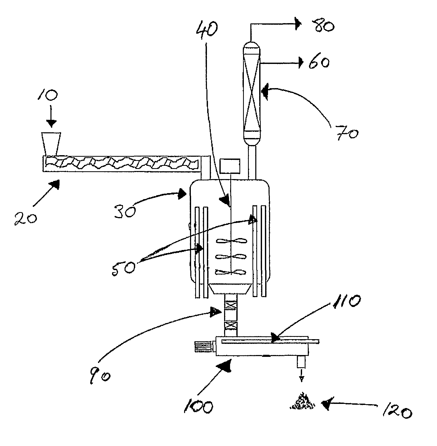
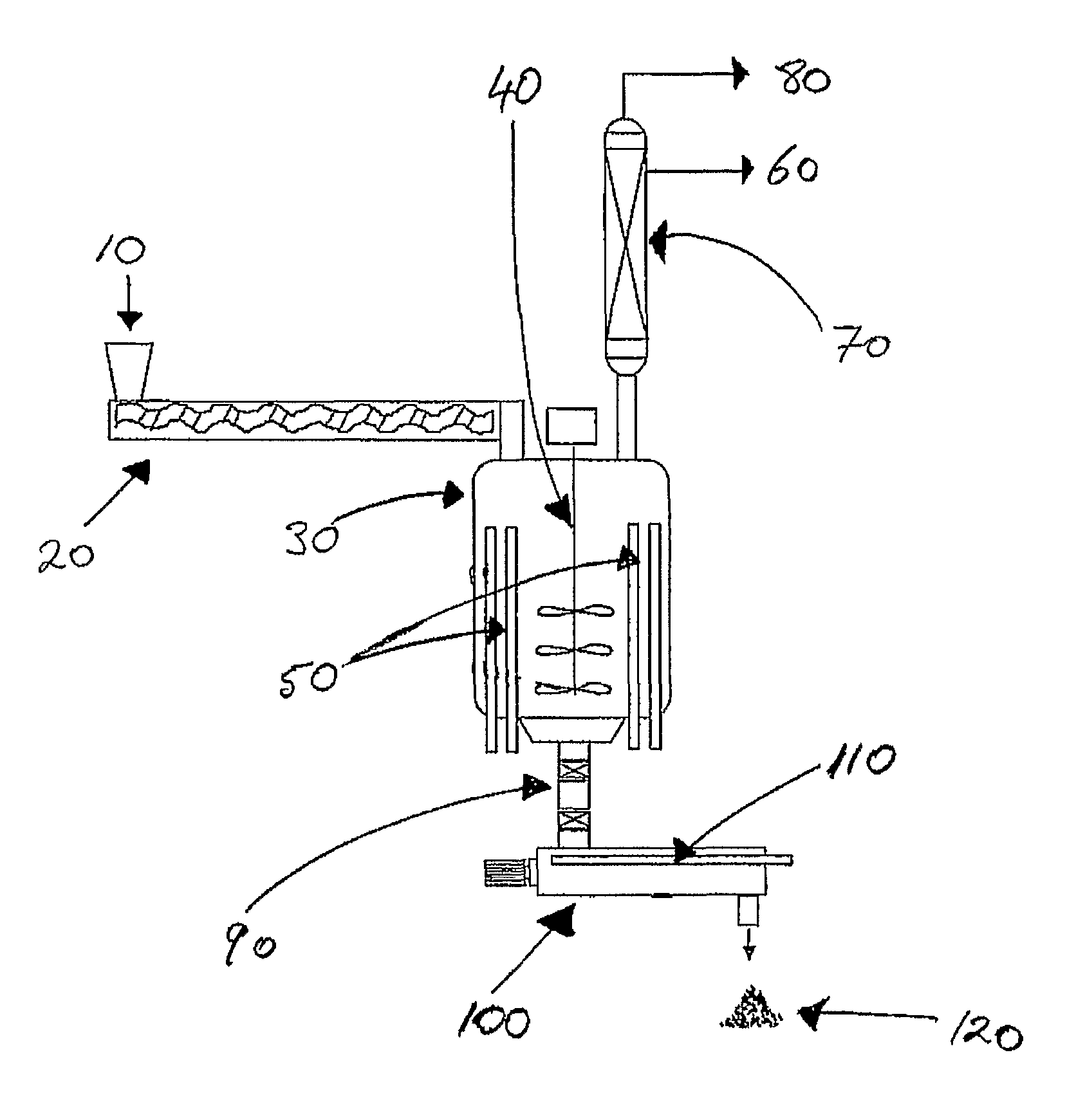
[0013]In contrast with common techniques for processing electrical and electronic equipment, the method of the present invention does not require diligent separation of metal components from plastic components, or the separation of the metal and plastic into their respective classes. In particular, provided that the electrical and electronic equipment can be melt processed, there is no limitation on the amount or type of metal and plastic components that may be present. This ability to tolerate both metal and plastic components vastly simplifies processing the equipment.
[0014]After melt processing the electrical and electronic equipment, the resulting melt processed product is transferred into a vessel where it is exposed into far infrared radiation (FIR). The FIR promotes heating of the product so as to convert plastic material in the product into volatile hydrocarbons and leaving behind non-volatile residue comprising metal. It has been found that the melt processed product can be heated rapidly and in a controlled manner using FIR as a means of heating. This step of the method in effect functions as a simple and efficient means of separating the plastic components from the metal components.
[0015]The ability to use in the method of the invention electrical and electronic equipment feedstock that has not undergone diligent separation of plastic and metal components, coupled with employing FIR heating to convert plastic in the feedstock into volatile hydrocarbons, is believed to collectively enhance the effectiveness, efficiency and safety of disposing of and recovering value added products from the feedstock.

Problems solved by technology

Furthermore, non-volatile residue resulting from the method comprises metal from the electrical and electronic equipment.

Method used


Image

  • Disposal of electrical and electronic equipment
  • Disposal of electrical and electronic equipment

Examples


example 1

[0063]WEEE comprising mainly printers and photocopiers was shredded using a Brentwood Industrial Shredders Quad-shaft (four shaft) shredder. Gross metal and glass was then removed from the shredded WEEE by metal separation (magnetic and Eddy current) and screening. The mixed plastics content of the resulting shredded WEEE was about 85 wt. % and comprised mainly HIPS, ABS, PC / ABS, Noryl (PPO-PS), and some polyolefins. The shredded WEEE was then melt processed (extruded) using a vented extruder at 250° C. and passed directly into a stainless steel (SS316) pyrolysis vessel. The melt processed product was then heated from within the vessel by 43 far infra-red heating rods (“inner heating”) to about 425° C. to promote pyrolysis of the plastic material. Volatile hydrocarbons liberated during pyrolysis were condensed and collected to yield about 70% (by weight of the melt processed product) of liquid comprised of a mixture of about 50% C11-C22 (diesel) plus about 20% ethyl benzene and abou...


PUM

PropertyMeasurementUnit
temperatureaaaaaaaaaa
temperaturesaaaaaaaaaa

Abstract

A method for disposing electrical and electronic equipment comprising plastic and metal components, the method comprising: melt processing the equipment and / or comminuted parts thereof to form a melt processed product; transferring the melt processed product into a vessel and heating the product using far infrared radiation such that it liberates volatile hydrocarbons and leaves behind non-volatile residue comprising metal; and collecting one or both of the volatile hydrocarbons and the non-volatile residue for subsequent use.

Description

FIELD OF THE INVENTION[0001]The present invention relates in general to the disposal of electrical and electronic equipment, and in particular to a method for disposing such equipment so as to recover usable products therefrom.BACKGROUND OF THE INVENTION[0002]As with most unwanted consumer products, unwanted electrical and electronic equipment eventually finds its way into municipal waste stations for disposal. Until recently, the most common method of disposal was to simply bury the waste electrical and electronic equipment (commonly referred to as “WEEE” or “e-waste”) in land-fill sites. However, with increased environmental awareness, there are growing concerns about disposing WEEE in this manner. For example, in the 1990's some European countries introduced laws banning the disposal of WEEE in land-fills.[0003]With the trend of banning the disposal of WEEE in land-fill sites expected to expand in the future, new techniques for disposing of the waste will need to be developed. If...

Claims


Application Information

Patent Timeline
Patent Type & Authority Patents(United States)
IPC IPC(8): B29K705/00C10B53/07B29B17/04C22B25/06B29B17/02B29L31/30C22B7/00C10G1/10
CPCB29B2017/0496B29L2031/3061C10G2300/205C10B53/07C10G2300/1003C10G2400/02C22B7/001C22B7/003B29K2705/00C22B25/06C10G1/10C10G2400/04B29B17/02Y02W30/54Y02W30/622Y02W30/625Y02P10/20Y02W30/62C22B7/00B09B5/00C08J11/00B09B3/00
Inventor SCHEIRS, JOHN
Owner P FUEL
Learn More