Flue gas composite phase change dust removal and desulfurization technology and device

A composite phase change and desulfurization device technology, which is applied in the field of desulfurization and dedusting tower technology and equipment, can solve the problems of limited water saturation adjustment range, high equipment cost and engineering cost, high risk of low-temperature corrosion, etc. The effect of flexible and reliable control and better operating economy

Active Publication Date: 2015-12-02
BEIJING CPCEP ENERGY CONSERVATION & ENVIRONMENTAL PROTECTION TECH CO LTD
View PDF6 Cites 22 Cited by
  • Summary
  • Abstract
  • Description
  • Claims
  • Application Information

AI Technical Summary

Problems solved by technology

[0004] The convective heat transfer technology is used to adjust the humidity of the flue gas. There are also some problems in this process: 1) The convective heat transfer can only increase the saturation of the moisture in the flue gas by simply reducing the temperature of the flue gas. The adjustment range of moisture saturation in medium is limited. In some special boiler tail gas, the moisture content is low. It is difficult to saturate the moisture simply by lowering the temperature, and the application range is limited; 2) The cooling efficiency of convective heat transfer to reduce the flue gas temperature is limited , because the heat exchange efficiency of this process is not only affected by the nature of the cold source, but also the characteristics of the heat exchange surface material also seriously affect the cooling range of the flue gas. The heat exchange efficiency of conventional heat exchange materials is not high, and a higher water saturation must be achieved 3) The convective heat transfer cooling process requires high heat transfer materials, not only requires a high heat transfer coefficient, but also requires high wear resistance and corrosion resistance, especially in the After the desulfurization tower, the temperature of the flue gas is low, and the risk of low-temperature corrosion is high. Special materials are required, and the equipment cost and engineering cost are high.

Method used


Image

  • Flue gas composite phase change dust removal and desulfurization technology and device
  • Flue gas composite phase change dust removal and desulfurization technology and device

Examples


Embodiment Construction

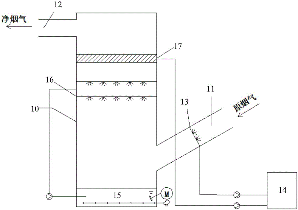
[0017] In order to better understand the purpose, structure and function of the present invention, a flue gas composite phase change dust removal and desulfurization process and device of the present invention will be further described in detail below in conjunction with the accompanying drawings.

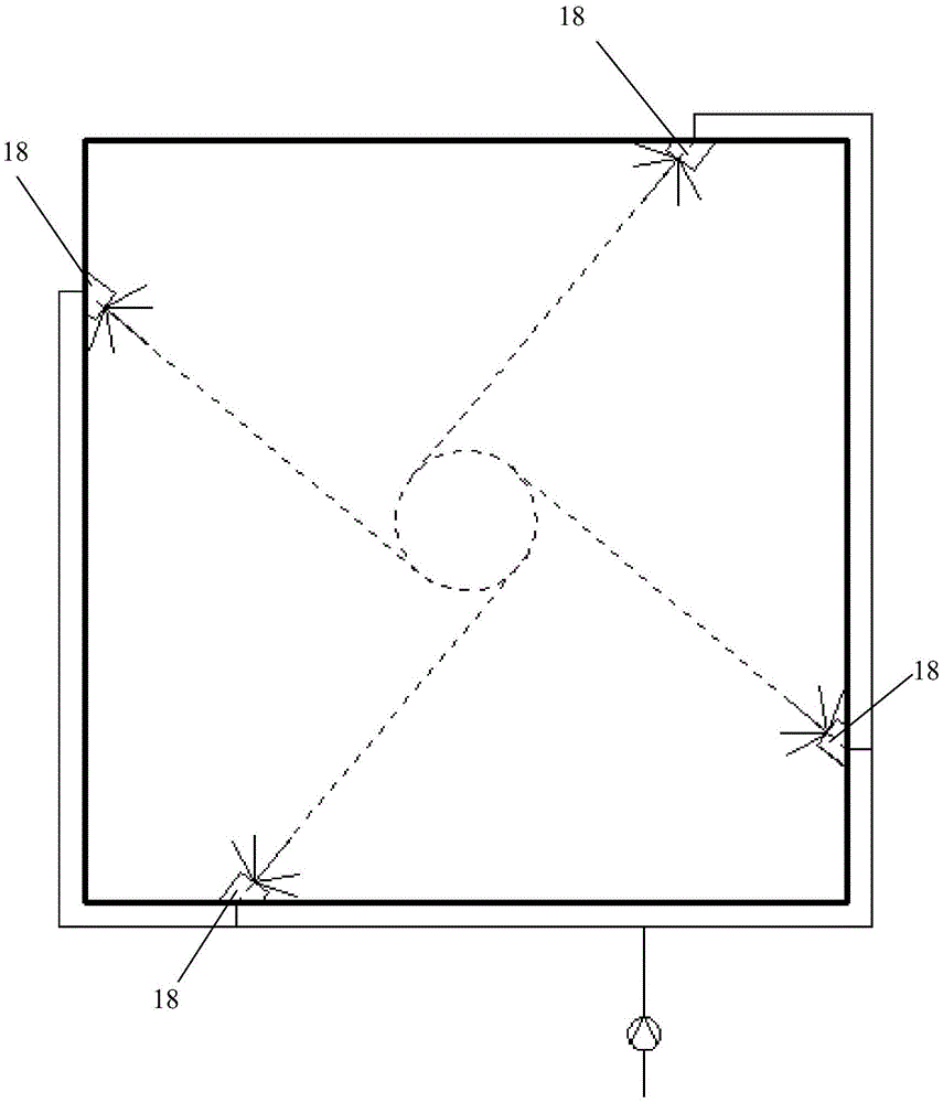
[0018] Such as figure 1 and figure 2 As shown, the flue gas composite phase change dust removal and desulfurization device of the present invention includes a desulfurization tower 10, the lower part of the side wall of the desulfurization tower 10 is connected with an inlet flue 11, and the upper part of the side wall is connected with an outlet flue 12. Wherein, the inlet flue 11 of the desulfurization tower 10 is provided with a vortex phase changer 13, and the vortex phase changer 13 is connected with a clean water tank 14 through a clean water pump.

[0019] Further, the vortex phase changer 13 includes multiple groups of atomizing nozzles 18, and the multiple groups of atom...


PUM


Abstract

The invention discloses a flue gas composite phase change dust removal and desulfurization device. The device comprises a desulfurizing tower (10). The lower portion of the side wall of the desulfurizing tower (10) is connected with an inlet flue (11). The upper portion of the side wall of the desulfurizing tower (10) is connected with an outlet flue (12). A vortex phase changer (13) is arranged on the inlet flue (11) of the desulfurizing tower (10) and comprises a plurality of sets of atomization nozzles (18). The atomization nozzles (18) are symmetrically arranged on the side wall of the inlet flue (11). Openings of the atomization nozzles (18) face the interior of the inlet flue (11) and are eccentrically arranged relative to the inlet flue (11). Spraying water sprayed by the atomization nozzles (18) in the vortex phase changer (13) can enable flue gas in the inlet flue (11) to generate rotational flow. The invention further discloses a flue gas composite phase change dust removal and desulfurization technology. The composite phase change condensation principle is utilized for enabling supersaturated water vapor to be condensed on the surfaces of fine particles, and the fine particle collection efficiency of the desulfurizing tower is improved.

Description

technical field [0001] The invention relates to the technical field of air pollution control, in particular to a desulfurization and dust removal tower process and equipment capable of simultaneous efficient desulfurization and dust removal integration, which is suitable for the treatment of industrial flue gas pollutants such as thermal power plants, industrial kilns, and coal-fired boilers. Background technique [0002] At present, the soot emission of coal-fired boilers is the focus of air pollution control. The main pollutants of coal-fired boiler flue dust are particulate matter, S0 2 , NO x Wait. Among them, particulate pollution, especially fine particulate matter, is the main culprit of atmospheric "smog". These fine particles float over the city for a long time, which not only seriously affects the visibility of the atmosphere, but also absorbs various pollutants (such as Hg, As, Pb and dioxin, etc.), and these particles are also important catalysts for photochem...

Claims


Application Information

Patent Timeline
Patent Type & Authority Applications(China)
IPC IPC(8): B01D53/80B01D53/50B01D50/00B01D47/06B01D53/18B01D53/14
Inventor 纳宏波江浩白云峰单选户初炜马志刚郭少鹏刘洋陈雪王德俊韩玉维刘亚
Owner BEIJING CPCEP ENERGY CONSERVATION & ENVIRONMENTAL PROTECTION TECH CO LTD
Why Eureka
Try Eureka