
Apparatus and method for applying a protective element on an optical waveguide

a protective element and optical waveguide technology, applied in the field of apparatus and method for applying a protective element on an optical waveguide, can solve the problems of large consumption of thermal output generated by the heating element, heat loss of the protective element, and heat transfer of the heating element to the protective element, so as to reduce electrical power consumption, reduce heat loss, and reduce power loss.

Active Publication Date: 2014-10-21
CCS TECH INC
View PDF11 Cites 10 Cited by
  • Summary
  • Abstract
  • Description
  • Claims
  • Application Information

AI Technical Summary

Benefits of technology

[0011]The transfer of the heat from the heating element to the protective element is effected by thermal radiation. The thermal radiation is emitted by the heating element, focused onto the protective element by the reflector and predominantly absorbed by the protective element. Given a suitable choice of the wavelength emitted by the heating element, the material for the reflective area of the reflector and the material for the protective element, it is possible to minimize the power loss due to heating of the reflector and the air within the device. As a result, for shrinking a protective element onto an optical waveguide, a lower thermal output and correspondingly a lower electrical power consumption than in the case of a conventional shrinking furnace are required. Moreover, the protective element more rapidly reaches a temperature at which the heat shrinking commences and the quantity of heat required for the shrinking process can be supplied in a shorter time. Therefore, with a limited supply of energy, it is possible for a higher number of protective elements to be shrunk onto optical waveguides in a shorter time.

Problems solved by technology

The heating brings about heat-shrinking of the protective element.
A conventional shrinking furnace has the disadvantage that the heat from the heating element is transferred to the protective element by thermal conduction via the trough and by convection via the air.
Therefore, a large part of the thermal output generated by the heating element is consumed for heating the trough and the air.
As a result, only small quantities of heat per unit time can be transferred directly from the trough to the protective element by thermal conduction.
However, the conventional shrinking furnace wastes a considerable amount of the generated energy for heating the heating element, the trough and the air.
This energy is no longer available for shrinking on protective elements or carrying out welding operations.
Accordingly, this results in an energy consumption of 900 Ws for the heating-up phase, an energy consumption of 675 Ws for the shrinking-on phase and a total duration of the shrinking-on operation of approximately 90 seconds.
Overall, it can be stated that the energy consumption and the time expended for shrinking a protective element onto an optical waveguide using a conventional shrinking furnace are unnecessarily high.

Method used


Image

  • Apparatus and method for applying a protective element on an optical waveguide
  • Apparatus and method for applying a protective element on an optical waveguide
  • Apparatus and method for applying a protective element on an optical waveguide

Examples


Embodiment Construction

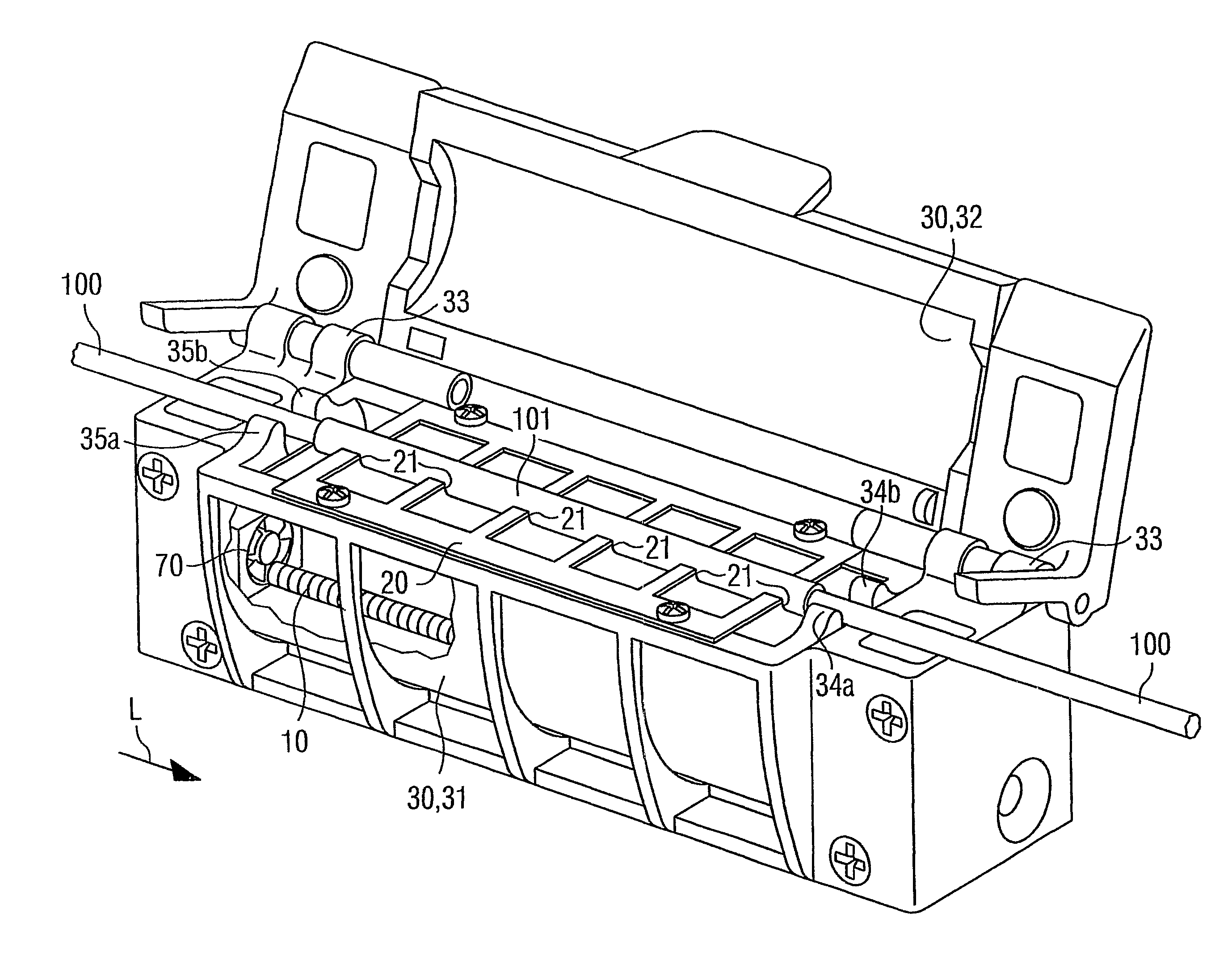
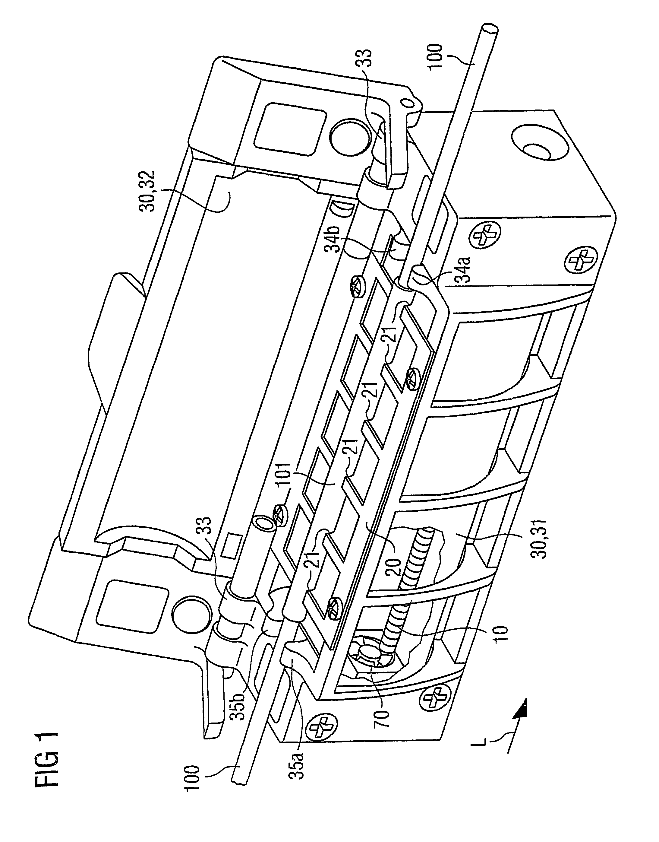
[0042]FIG. 1 perspectively illustrates an exemplary embodiment of the device according to the invention for shrinking a protective element 101 onto an optical waveguide 100.

[0043]The device comprises a heating element 10, a mount for the optical waveguide 100 and a reflector 30, which are accommodated in a common housing, for example comprised of injection molding or plastic material. The protective element 101 surrounds a section of the optical waveguide 100. The optical waveguide 100 and the protective element 101 surrounding it extend in a longitudinal direction L.

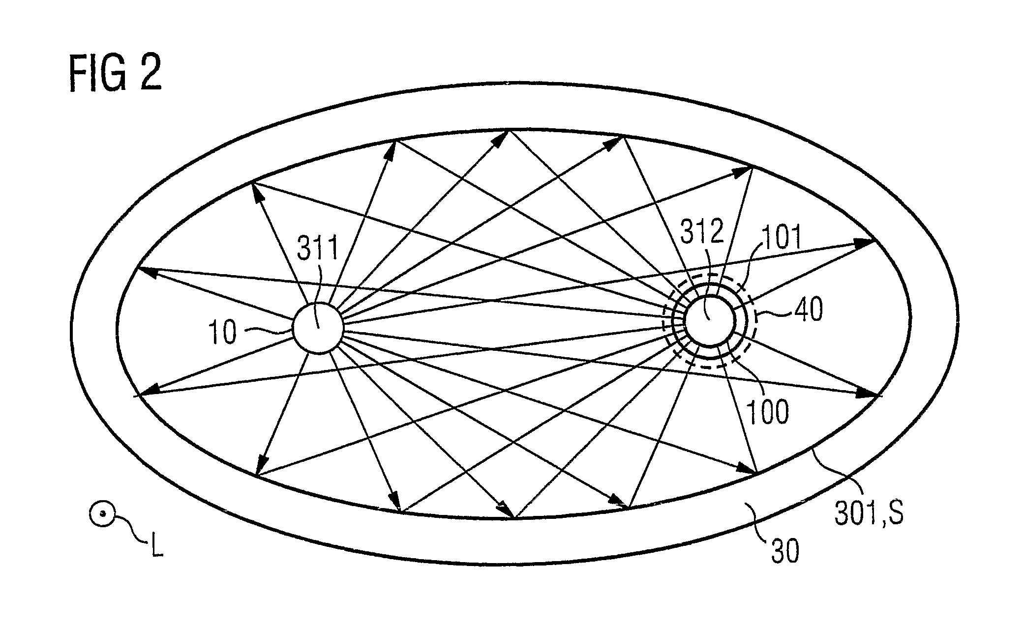
[0044]The reflector 30 extends in the longitudinal direction L over a specific length, is embodied as a hollow body and is integrated into the housing. The reflector 30 comprises a reflective area having identical cross sections in the form of ellipses over the entire length of the reflector 30 with regard to the longitudinal direction L. One of the ellipses in each case has a first and a second focal point. A first foc...


PUM

PropertyMeasurementUnit
power consumptionaaaaaaaaaa
thermal radiationaaaaaaaaaa

Abstract

A device and a method are provided, for shrinking a protective element (101) shrinkable by means of the supply of heat onto an optical waveguide (100). The method involves generating thermal radiation, reflecting it and focusing it onto a focus zone in which the protective element (101) is held. The device contains a heating element (10), which generates thermal radiation, a reflector (30), which focuses the thermal radiation emitted by the heating element onto the focus zone, and a mount (20), by means of which the protective element (101) can be held in the focus zone.

Description

[0001]The invention relates to a device and a method for fitting a heat-shrinkable protective element onto a section of an elongated element, in particular of an optical waveguide.BACKGROUND OF THE INVENTION[0002]In order that optical waveguides can be welded to one another by means of fusion welding, for example, the optical waveguides are uncovered in the vicinity of the locations to be welded. For this purpose, fiber coatings surrounding the optical waveguides are removed. After the optical waveguides have been welded to one another, for example, they are protected against ambient influences and mechanical damage. Protection for an exposed optical waveguide may also be necessary for other reasons.[0003]A protective element shrinkable by means of the supply of heat is usually used for protecting a previously uncovered optical waveguide. The protective element is embodied as a tube made of a material shrinkable by means of the supply of heat, for example a polymer. The protective e...

Claims


Application Information

Patent Timeline
Patent Type & Authority Patents(United States)
IPC IPC(8): B29C63/42B29D11/00B29C61/00G02B6/255A45D20/40H05B3/02
CPCG02B6/2558B29C61/00B29D11/00663B29C63/42Y10T29/49908
Inventor ZAMZOW, BERT
Owner CCS TECH INC
Learn More