Work Machine

a work machine and work shaft technology, applied in the field of work machines, can solve the problems of time and trouble, complicated structure of the transmission case, etc., and achieve the effect of preventing the leakage of operating oil

Active Publication Date: 2021-07-01
KUBOTA LTD
View PDF0 Cites 0 Cited by
  • Summary
  • Abstract
  • Description
  • Claims
  • Application Information

AI Technical Summary

Benefits of technology

[0017]With the above characteristic arrangement, the supply passage is orthogonal to the case axis. This allows operating oil to be supplied from the first hydraulic unit to the second hydraulic unit over the shortest distance. Further, the supply passage is in a straight line. This reduces the passage resistance of the supply passage.
[0024]The above arrangement allows the supply passage to be formed from an in-pipe oil passage in the pipe-shaped member and a hole-shaped oil passage in the internal member. Further, the above arrangement uses a pipe-shaped member for a portion of the supply passage. If, for instance, there is a slight error between (i) the position of that port which serves to supply operating oil to the first hydraulic unit or the second hydraulic unit and (ii) the axis of the supply passage, slightly deforming the pipe-shaped member allows the pipe-shaped member to be connected easily.
[0035]The above arrangement allows the supply passage to be present at a position other than the position of the support section supporting the clutch shaft of the clutch mechanism. The internal member (which is integral with the respective inner surfaces of the wall portions) may, for instance, include a support section supporting the clutch shaft. This eliminates the need to include such a support section as a separate member.
[0041]With the above arrangement, at least one of the first hydraulic unit and the second hydraulic unit is attached to a wall portion of the transmission case in such a manner as to be in close contact therewith. This not only allows stable attachment, but also prevents leakage of operating oil.

Problems solved by technology

However, the transmission case will have a complicated structure, and there is room for improvement in transmission case production that requires time and trouble.

Method used


Image

  • Work Machine
  • Work Machine
  • Work Machine

Examples


Embodiment Construction

[0050]An embodiment of the invention will be described hereinafter with reference to the drawings.

[Overall Configuration]

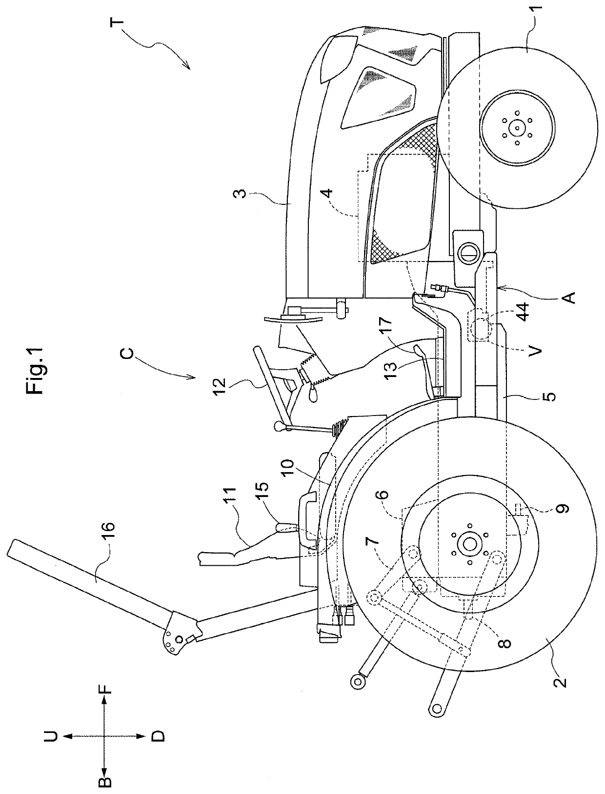
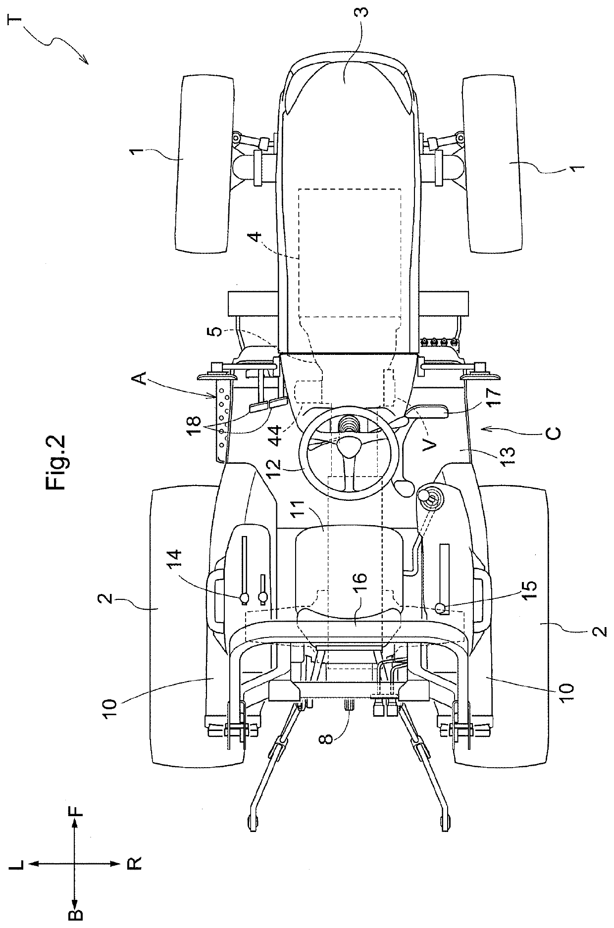
[0051]As shown in FIGS. 1 and 2, a tractor T is illustrated as an exemplary work machine (work vehicle), including a machine body A provided with a pair of right and left front wheels 1 and a pair of right and left rear wheels 2; an engine 4 covered by an engine hood 3 at a forward portion of the machine body A; and a driver section C at a rear portion of the machine body A.

[0052]In following description, “F” shown in FIGS. 1 and 2 depicts to indicate the forward direction, “B” the backward direction, “U” the upward direction, “D” the downward direction, “R” the rightward direction, and “L” the leftward direction.

[0053]The tractor T further includes: a transmission case 5 in an area extending from a central portion of the machine body A to the back end thereof for varying the driving force of the engine 4; a lift cylinder 6 housed in the transmission case 5 at a r...


PUM


Abstract

A work machine includes a transmission case (5) extending in the front-back direction of a machine body, a first hydraulic unit (V) provided on one of mutually opposite wall portions (5a, 5b) of the transmission case (5), a second hydraulic unit (44) provided on a second one of the wall portions (5a, 5b), and a supply passage (43) configured to supply operating oil from the first hydraulic unit (V) to the second hydraulic unit (44). The first hydraulic unit (V) and the second hydraulic unit (44) are aligned to be overlapped with each other as viewed in a direction orthogonal to a case axis (X) extending along the front-back direction of the transmission case (5). The supply passage (43) extends inside the transmission case (5) in a straight line orthogonal to the case axis (X).

Description

CROSS-REFERENCE TO RELATED APPLICATION[0001]This application claims priority to Japanese Patent Application No. 2019-237397 filed Dec. 26, 2019, the disclosure of which is hereby incorporated by reference in its entirety.BACKGROUND OF THE INVENTION1. Field of the Invention[0002]The present invention relates to a work machine including a transmission case, and a unit provided on an outer surface of the transmission case to be supplied with operating oil.2. Description of the Related Art[0003]A work machine is disclosed in JP H06-199140 A, for example.[0004]In JP H06-199140 A, a tractor includes a casing of a continuously variable transmission device is connected to a transmission case; and an oil filter is provided on an outer wall of the casing. An oil passage is formed in the transmission case, etc. to supply operating oil stored in the transmission case as charge oil for the continuously variable transmission device.[0005]Specifically, JP H06-199140 A discloses an oil passage conf...

Claims


Application Information

Patent Timeline
Patent Type & Authority Applications(United States)
IPC IPC(8): E02F9/22B60K17/28
CPCE02F9/2296F16H37/042B60K17/28F16H57/0424F16H47/02F16H2057/02056B60K17/06B60K17/02B60K2025/024B60Y2200/221F15B2211/50518
Inventor NAKAYAMA, DAISUKENOGAMI, HIRONOBUTOTTORI, NORITAOKAMOTO, NAOYA
Owner KUBOTA LTD
Why Eureka
Try Eureka