Dust removing device and image pickup apparatus

a technology of image pickup and dust removal device, which is applied in the direction of carpet cleaners, television systems, instruments, etc., can solve the problems of insufficient amplitude of vibration near piezoelectric elements, insufficient amplitude of vibration, and foreign matter adhesion to the surface, so as to reduce the area and effectively remove the effect of dus

Inactive Publication Date: 2014-10-21
CANON KK
View PDF30 Cites 6 Cited by
  • Summary
  • Abstract
  • Description
  • Claims
  • Application Information

AI Technical Summary

Benefits of technology

[0011]The present invention provides a dust removing device that effectively removes dust by reducing the area where the amplitude of vibration tends to be small, and an image pickup apparatus including the same.

Problems solved by technology

Consequently, such foreign matter may adhere to the surface of the cover glass of the image pickup device or the filter.
Consequently, the amplitude of vibration is insufficient.
In the configuration disclosed by Japanese Patent Laid-Open No. 2004-12474 also, the amplitude of vibration near the piezoelectric elements is considered to be insufficient.

Method used


Image

  • Dust removing device and image pickup apparatus
  • Dust removing device and image pickup apparatus
  • Dust removing device and image pickup apparatus

Examples


working example 1

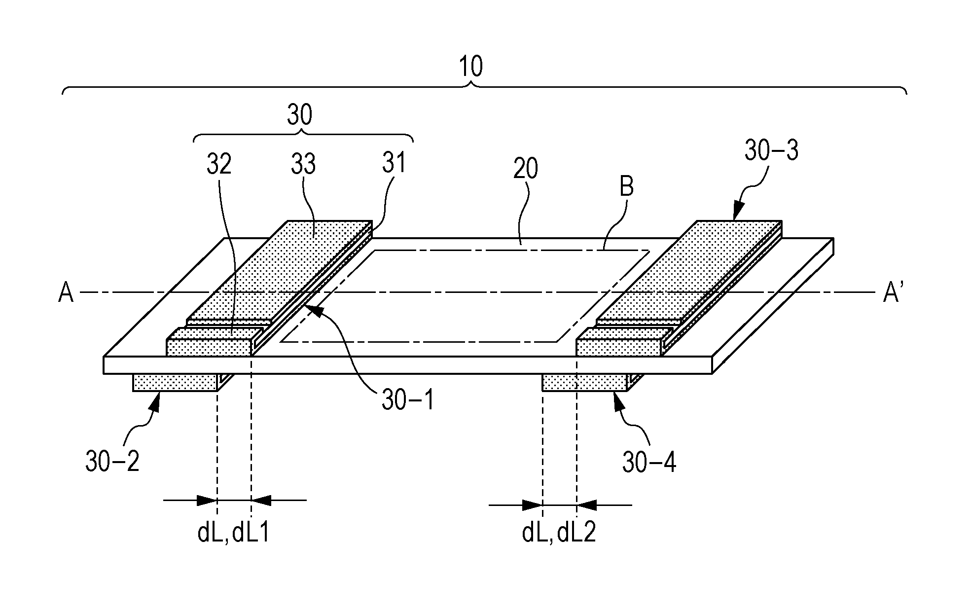
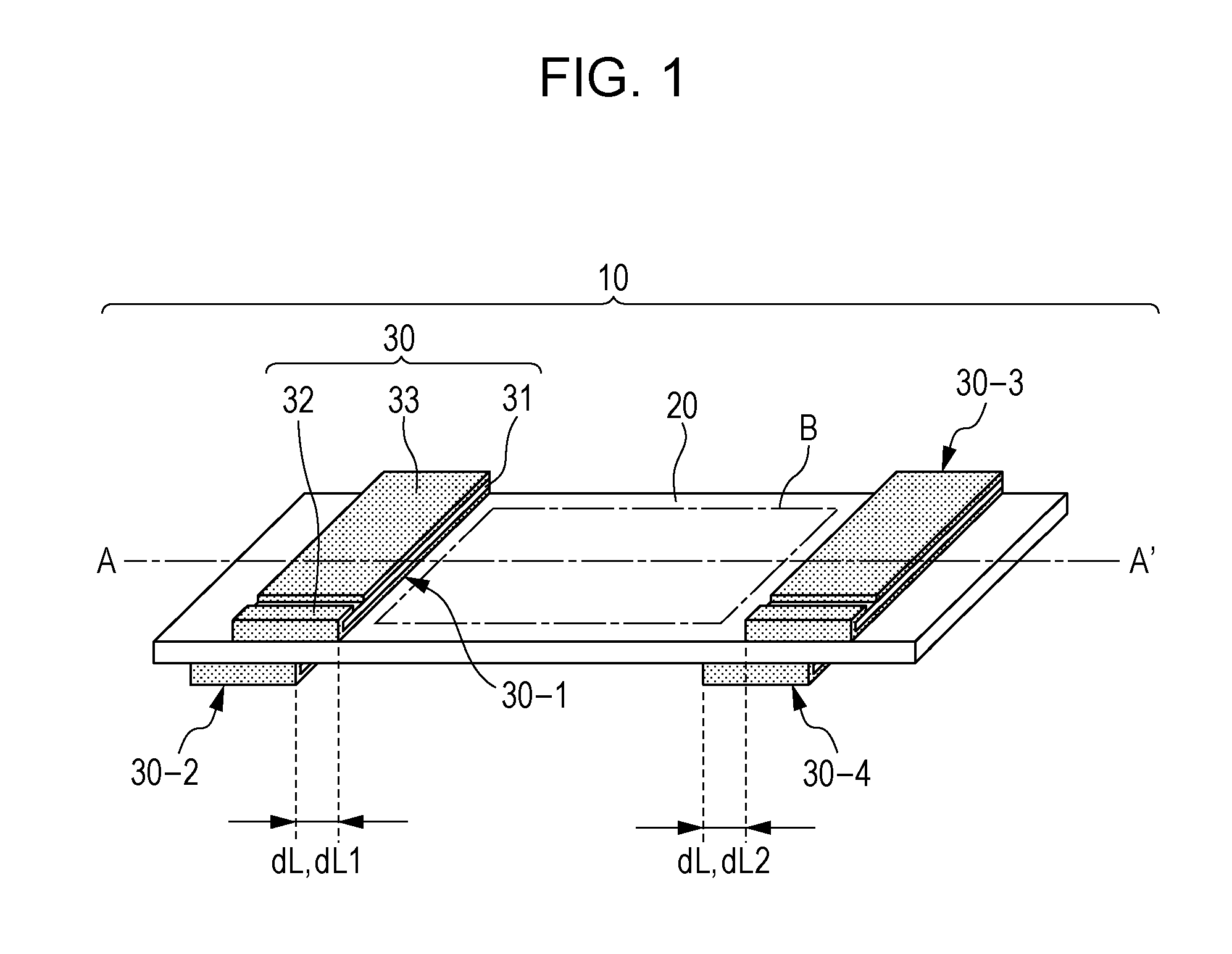
[0081]A dust removing device 10 configured as illustrated in FIG. 1 was prepared by using a vibrating plate 20 that was a glass plate functioning as an infrared cut filter and of size 50.8 mm (width)×33.7 mm (length)×0.3 mm (thickness) and piezoelectric elements 30 each made of PZT having a material code NA manufactured by Nihon Ceratec Co., Ltd. (with Ag-paste electrodes, polarized) and being of size 33.3 mm×4.0 mm×0.25 mm. The piezoelectric elements 30 were fixed at the positions illustrated in FIG. 1 with epoxy-resin-based adhesive applied in the longitudinal direction, corresponding to the length of 33.7 mm, of the vibrating plate20. The piezoelectric elements 30 were arranged on the vibrating plate 20 such that the distances dL fell within a range of λ / 4±3%, where λ denotes the wavelength of vibration generated at the resonance frequency of the piezoelectric elements 30. In Working Example 1, dL=dL1=dL2, and the optically effective area (target surface B enclosed by the dash-do...

working example 2

[0085]A dust removing device 10 configured as illustrated in FIG. 1 was prepared by using the same vibrating plate 20 and the same piezoelectric elements 30 as those used in Working Example 1 and such that the distances dL each became λ / 8. In Working Example 2, dL=dL1=dL2. As with Working Example 1, the removal driving operations A to D were performed sequentially. As with Working Example 1, a bending vibration mode of the nineteenth order was generated when the phase difference was 0, and a bending vibration mode of the eighteenth order was generated when the phase difference was π. In Working Example 2, the smallest amplitude of vibration observed in the optically effective area was 0.80 μm, and the level of dust removal performance was 3.

working example 3

[0086]A dust removing device 10 configured as illustrated in FIG. 6 was prepared by using the same vibrating plate 20 and the same piezoelectric elements 30 as those used in Working Example 1 and such that the distance dL became λ / 4. Removal driving operations were performed as follows. The alternating voltage of the same value and at the same frequency as those defined for the removal driving operation A performed in Working Example 1 was applied first to the piezoelectric element 30-1 and then to the piezoelectric element 30-2 once each (for a duration of one second or less). That is, the alternating voltage was applied to the two piezoelectric elements 30-1 and 30-2 sequentially at different timings. In Working Example 3, a bending vibration mode of the nineteenth order was generated both in the application of the alternating voltage to the piezoelectric element 30-1 and in the application of the alternating voltage to the piezoelectric element 30-2. In Working Example 3, the sma...


PUM


Abstract

A dust removing device generates vibrations at least at a wavelength λ in a vibrating member by applying alternating voltages to a first piezoelectric element and a second piezoelectric element, respectively. The first piezoelectric element is provided on a first surface of the vibrating member that is on a side having a target surface. The second piezoelectric element is provided on a second surface of the vibrating member that is opposite the first surface. When the first piezoelectric element and the second piezoelectric element are projected in a direction that is normal to the target surface, a distance dL1 between a vibration generating end of the first piezoelectric element and a vibration generating end of the second piezoelectric element is expressed in the form dL1>0, where dL1≠nλ / 2 and n is a positive integer.

Description

BACKGROUND OF THE INVENTION[0001]1. Field of the Invention[0002]The present invention relates to a dust removing device and an image pickup apparatus, and particularly to the removal of foreign matter such as dust adhering to a surface of an optical member provided in an image pickup apparatus such as a digital camera or in an image reading apparatus such as a scanner.[0003]2. Description of the Related Art[0004]In an image pickup apparatus such as a digital camera that picks up an image of an object by receiving an optical image of the object and then converting the optical image into an electrical signal, light that is taken thereinto is received by an image pickup device such as a charge-coupled-device (CCD) sensor or a complementary-metal-oxide-semiconductor (CMOS) sensor. The electrical signal (photoelectric conversion signal) is output from the image pickup device, is converted into image data, and is recorded on a recording medium such as a memory card. In such an image picku...

Claims


Application Information

Patent Timeline
Patent Type & Authority Patents(United States)
IPC IPC(8): H04N5/217G02B27/00H04N5/225B60R1/06
CPCH04N5/2171G02B27/0006H04N5/2254H04N23/811H04N23/52
Inventor SHIMIZU, YASUSHIIFUKU, TOSHIHIROFURUTA, TATSUO
Owner CANON KK
Why Eureka
Try Eureka