Switching power source and image forming apparatus
a technology of image forming apparatus and power source, which is applied in the direction of digital output to print units, process and machine control, instruments, etc., can solve the problems of affecting the sound quality of the image, the sound is unfavorable to the human ear, and the frequency of the switch is reduced much more, so as to reduce the beat sound, reduce the loss, and increase the size of the transformer
- Summary
- Abstract
- Description
- Claims
- Application Information
AI Technical Summary
Benefits of technology
Problems solved by technology
Method used
Image
Examples
third exemplary embodiment
[0096]Next, a third exemplary embodiment will be described based on FIG. 14. The same reference numerals are assigned to the parts having configurations and functions similar to those in the above-described conventional example and the first and second exemplary embodiments, and therefore descriptions thereof will not be repeated.
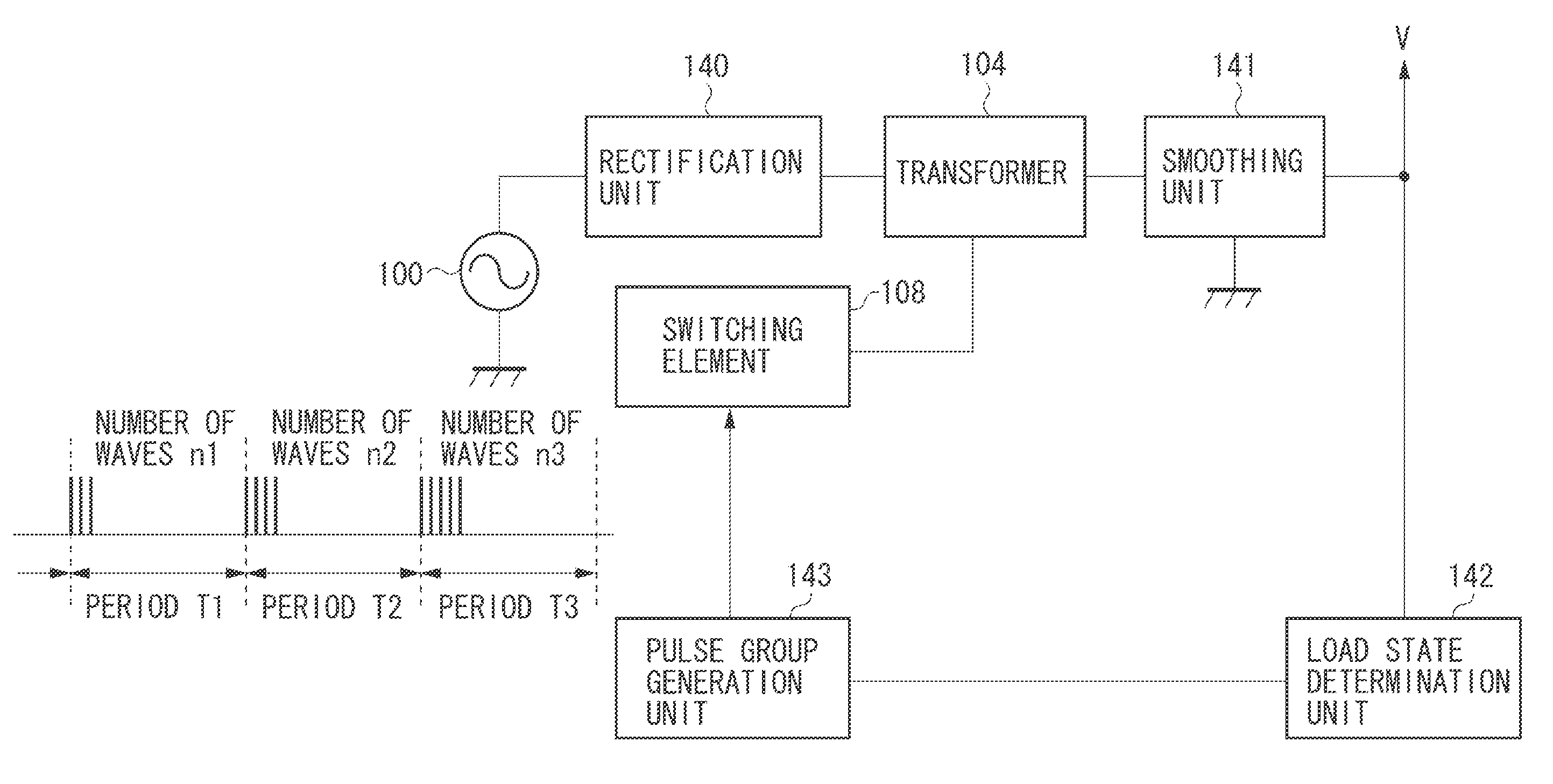
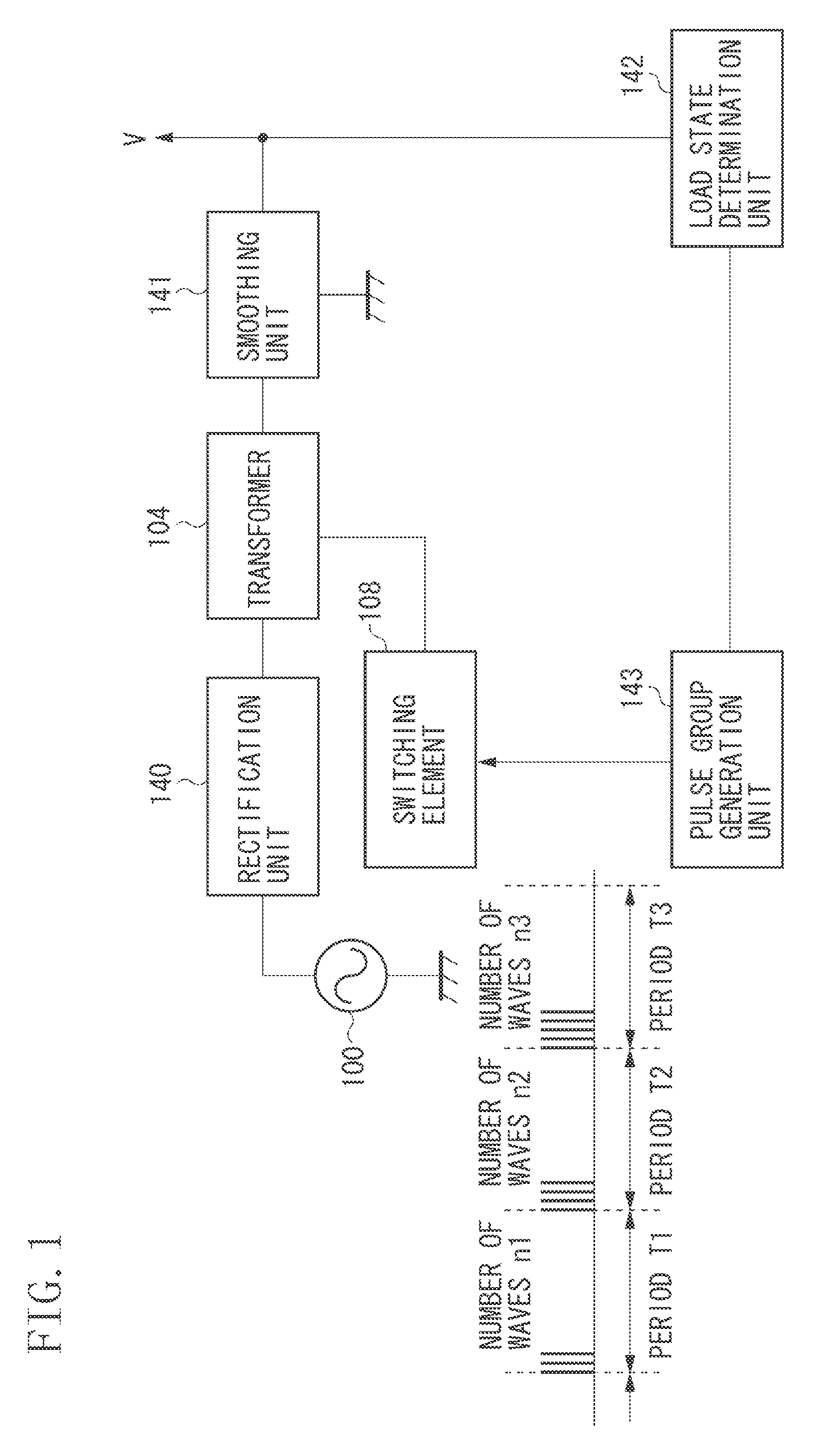
[0097]The features of the present exemplary embodiment are as illustrated in the control block of the CPU 121 in FIG. 4. Variable patterns of a number of driving pulses for each burst cycle is determined by a random number generation unit 129 provided inside the CPU 121, which is different from the first and second exemplary embodiments. In the first and second exemplary embodiments, the number of pulses ni in the driving pulse group is regularly (cyclically) added or subtracted in increment or decrement of one wave, in such a manner as 3→wave→4→wave→5→wave→4→wave→3→wave→4→wave→●●●, and the number of driving pulses is controlled to be scattered so that the ...
modified example 1
[0101]Modified examples of a varying method for number of pulses will be described. FIG. 19 illustrates transformer driving current waveforms, and driving pulse waveforms in a case where the number of pulses (number of waves) is set to the variable patterns in such a manner as “1→wave→1→wave→2→wave→1→wave→1→wave→2→wave→●●●”. In FIG. 19, transformer driving current waveforms, and driving pulse waveforms are illustrated when the FET 1081 is driven in a driving pulse group in a cycle of 1 msec (cycles T1, T2, and T3 in FIG. 8), ON-period of 2.5 μsec and OFF-period of 20 μsec between the driving pulses. Further, the results of having performed frequency analysis (fast-Fourier transform analysis (FFT analysis)), with respect to the transformer driving current waveforms in FIG. 19 are illustrated in FIG. 20. As illustrated in FIG. 20, compared with the FFT spectrum when switching operation is performed with the driving pulse of 1-wave during the light-load running described in FIG. 17 in ...
modified example 2
[0102]FIG. 21 illustrates transformer driving current waveforms, and driving pulse waveforms in a case where the number of pulses (number of waves) is set to the variable patterns in such a manner as “1→wave→1→wave→2→wave→1→wave→1→wave→2→wave→●●●”. Further, FIG. 22 illustrates the results of having performed frequency analysis (FFT analysis), with respect to the transformer driving current waveforms in FIG. 21. As illustrated in FIG. 22, the spectrum reduction similar to the above-described example (modified example 1) is performed. In this way, as long as the variable patterns are made such that the number of pulses is scattered to become the predetermined number of pulses on average, it can be found that the harmonic wave components are reduced.
PUM
 Abstract
Description
Claims
Application Information
 - R&D
- Intellectual Property
- Life Sciences
- Materials
- Tech Scout
- Unparalleled Data Quality
- Higher Quality Content
- 60% Fewer Hallucinations
Browse by: Latest US Patents, China's latest patents, Technical Efficacy Thesaurus, Application Domain, Technology Topic, Popular Technical Reports.
© 2025 PatSnap. All rights reserved.Legal|Privacy policy|Modern Slavery Act Transparency Statement|Sitemap|About US| Contact US: help@patsnap.com


