Ignition system and method for igniting fuel in a vehicle engine by means of a corona discharger

a technology of ignition system and fuel, which is applied in the direction of engine ignition, electric ignition installation, electrical control, etc., can solve the problems of putting a considerable load on the electrical system of the vehicle, and affecting the service life of the engin

Active Publication Date: 2014-10-28
BORGWARNER BERU SYST
View PDF7 Cites 8 Cited by
  • Summary
  • Abstract
  • Description
  • Claims
  • Application Information

AI Technical Summary

Benefits of technology

[0003]The ignition of fuel using corona discharges is an alternative to conventional spark plugs which induce ignition by means of an arc discharge and are subject to considerable wear due to electrode erosion. Corona ignitions have the potential to reduce costs considerably and improve fuel combustion. However, HF ignition systems have a high power demand and therefore place a considerable load on the electrical system of a vehicle.
[0005]An ignition system according to the invention comprises an energy accumulator for charging from the electrical system of the vehicle, which is connected to the input side of the voltage converter, e.g. the primary side of a transformer, to even out the electrical system load. In the case of an ignition system according to the invention, the energy required to generate a corona discharge, which occurs in a pulsed manner in accordance with the engine phase, can therefore be covered at least partially from the energy accumulator of the ignition system. Given that the energy accumulator is charged between the current pulses supplied to the input side of the voltage converter, the electric energy required for the individual current pulses can be taken from the electrical system of the vehicle over a longer period of time and, therefore, more evenly. A pulse-type load, which is problematic for the vehicle electrical system, i.e. drawing large currents in short time intervals, can therefore be reduced using an ignition system according to the invention, and can be replaced by a more even load, namely drawing smaller currents over a longer period of time.
[0006]The energy accumulator of an ignition system according to the invention is preferably a capacitor. Capacitors can advantageously release stored electric energy in a short period of time and are therefore well suited to generating current pulses, which must be supplied to the input side of a voltage converter to generate a corona discharge.
[0012]In a further advantageous refinement of the invention, the intensity and / or the course of a charging current over time, with which the energy accumulator is charged via the electrical system, is controlled depending on the speed of the engine, e.g. in that the control unit specifies the duty factor t / T and / or the period T for charging using a method of pulse-width modulation. Since the interval between the corona discharges is specified by the engine speed, optimal use of the time that is available for charging the energy accumulator can be made in this manner, and so the load on the electrical system associated with charging can be distributed across the longest period of time possible.
[0013]In another advantageous refinement of the invention, the charging current is controlled depending on an expected demand for ignition energy, The ignition energy required to ignite the fuel depends on the operating state of the engine. By evaluating the state data of the engine, e.g. engine load, speed, quantity of fuel injected, and / or engine temperature, an expected demand for ignition energy can therefore be determined, In the simplest case, the value of the energy consumed in the last ignition can be used as the value for the expected energy demand for the next ignition. Given that the expected demand for ignition energy is supplied to the energy accumulator during a working cycle, the load on the electrical system can be evened out further.

Problems solved by technology

The ignition of fuel using corona discharges is an alternative to conventional spark plugs which induce ignition by means of an arc discharge and are subject to considerable wear due to electrode erosion.
However, HF ignition systems have a high power demand and therefore place a considerable load on the electrical system of a vehicle.

Method used


Image

  • Ignition system and method for igniting fuel in a vehicle engine by means of a corona discharger
  • Ignition system and method for igniting fuel in a vehicle engine by means of a corona discharger
  • Ignition system and method for igniting fuel in a vehicle engine by means of a corona discharger

Examples


Embodiment Construction

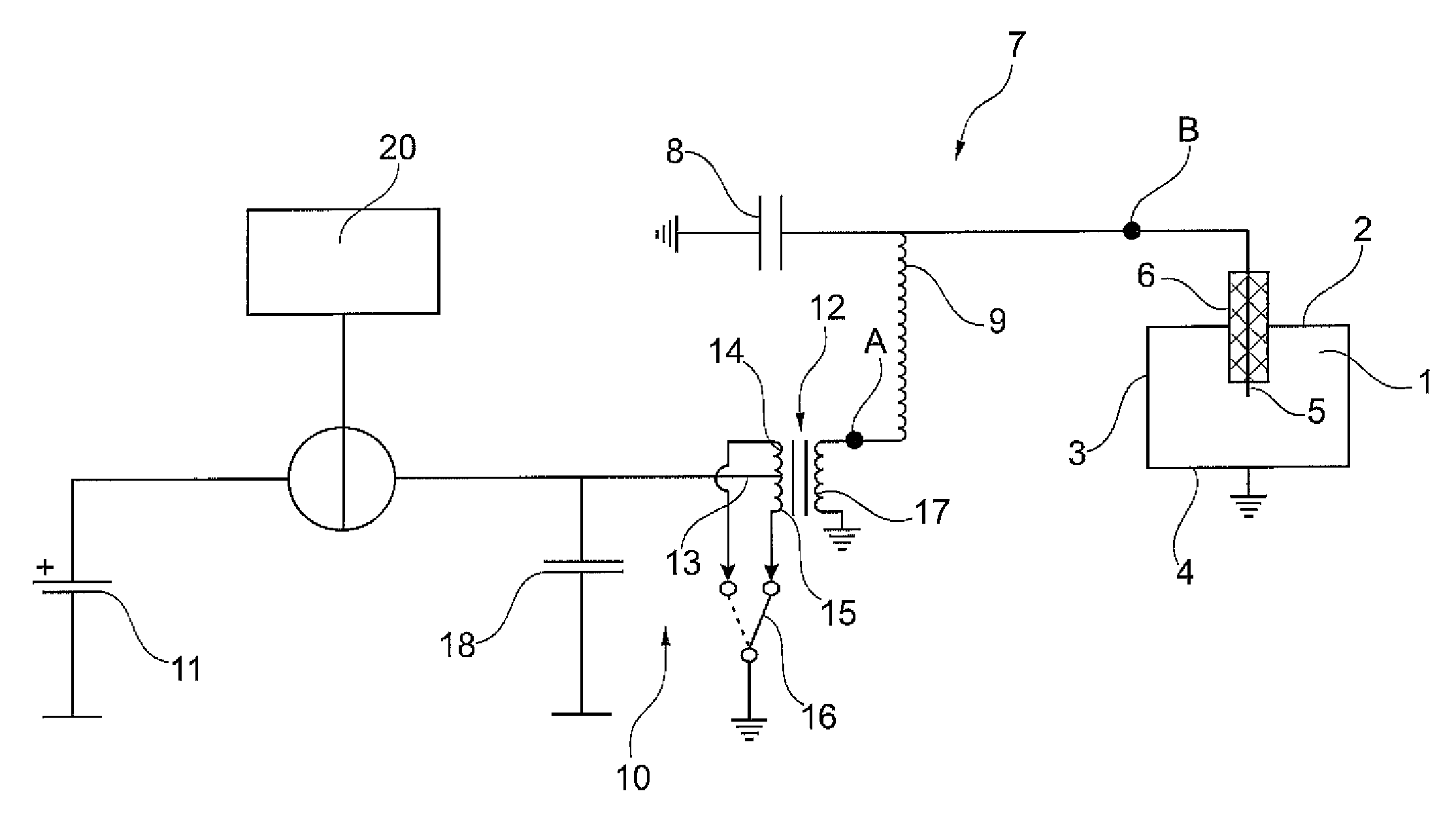
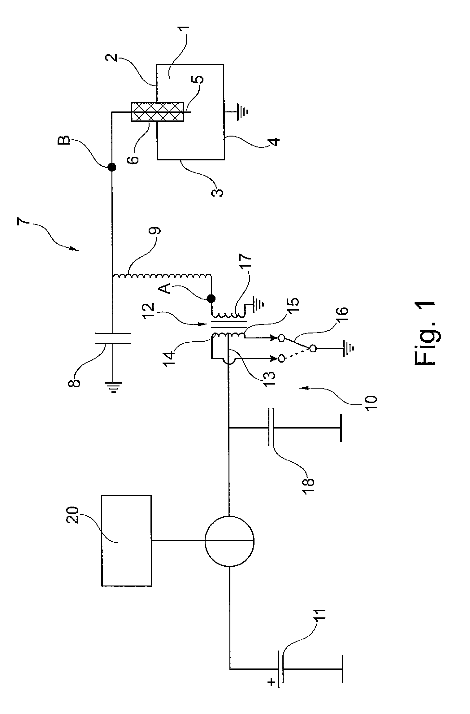
[0020]FIG. 1 shows a schematic depiction of a combustion chamber 1 of a cyclically operating internal combustion engine. The combustion chamber is delimited by walls 2, 3, 4 which are at ground potential. An insulator 6 that carries an ignition electrode 5 extends into combustion chamber 1. Ignition electrode 5 is electrically insulated by insulator 6 with respect to walls 2, 3, 4. Ignition electrode 5 and walls 2, 3, 4 of combustion chamber 1 are part of a series oscillating circuit 7 which also includes a capacitor 8 and an inductor 9. Of course, series oscillating circuit 7 can also comprise further inductors and / or capacitors, and other components that are known to a person skilled in the art as possible components of oscillating circuits.

[0021]A high-frequency generating unit for the excitation of oscillating circuit 7, such as a high-frequency generator 10, is provided, which comprises a voltage converter, preferably a transformer 12 having a center tap 13 on the input or prim...


PUM


Abstract

The invention relates to an ignition system for the ignition of fuel in a vehicle engine by means of a corona discharge, comprising a voltage converter which has an input side for connection to a voltage source, and an output side, and an electric oscillating circuit connected to the secondary side for HF excitation of an ignition electrode. According to the invention, by an energy accumulator for charging from the electrical system of a vehicle, the energy accumulator being connected to the input side of the voltage converter to even out the electrical system load. The invention furthermore relates to a method according to the invention for the ignition of fuel.

Description

[0001]The invention refers to an ignition system for igniting fuel in a vehicle engine by means of a corona discharge. Such ignition systems are usually referred to as corona or HF ignition systems. The invention furthermore relates to a method for igniting fuel in a vehicle engine by means of a corona discharge. Such an ignition system and a corresponding method are known from EP 1 515 594 A2.[0002]HF ignition systems generate—on the basis of a vehicle system voltage using a voltage converter, e.g. a transformer—a high voltage which is used for the HF excitation of an electric oscillating circuit to which the ignition electrode is connected. HF ignition systems therefore have a voltage converter that comprises an input side for connection to the electrical system of a vehicle, and an output side which is connected to an electric oscillating circuit for HF excitation of an ignition electrode. The resonant frequency of the oscillating circuit is typically between 30 KHz and 3 MHz. Th...

Claims


Application Information

Patent Timeline
Patent Type & Authority Patents(United States)
IPC IPC(8): F02P23/04F02P9/00F02P23/00F02D41/20
CPCF02P9/002F02P23/045F02D2200/503F02D2041/2027F02P3/01
Inventor BRAEUCHLE, GERD
Owner BORGWARNER BERU SYST
Why Eureka
Try Eureka