Directional speed and distance sensor

a technology of directional speed and distance measurement, applied in the direction of traffic control supervision, using reradiation, instruments, etc., can solve the problems of inability to achieve true inability to accurately measure the speed and distance of the sensor, and inability to use real time-of-flight ranging with radar or laser. , to achieve the effect of being convenient, effective and economical

Active Publication Date: 2014-10-28
SUBRAMANYA BALU
View PDF146 Cites 31 Cited by
  • Summary
  • Abstract
  • Description
  • Claims
  • Application Information

AI Technical Summary

Benefits of technology

[0009]There is also a significant need in many applications to uniquely identify a vehicle at a parking space or an access control point. For example, this information can be used to provide discounts, preferential treatment of vehicles, or to apply different enforcement or business rules. One elegant, economical, and effective way of accomplishing this is to combine the sensor's low power transmission with data and achieve one way or two communications with a compatible in-vehicle device. The disclosed invention makes this possible by combining a range of disclosed features including low power transmissions that are repeated frequently, highly localized transmissions in the zone of interest, techniques that use the transmission and reception capabilities in the radar to also communicate low data rate information such as an unique vehicle identification, and techniques that enables the sensor to distinguish between target object radar signatures from transmissions from the in-vehicle devices. The disclosed techniques also make it possible for very low powered in-vehicle devices that can operate on small battery or solar power.

Problems solved by technology

Other sensing technologies exist, such as Doppler techniques with Radar, Laser, or Ultrasound, Frequency Modulated Continuous Wave techniques with Radar, Laser, Infrared, or Ultrasound, Time of flight ranging with Ultrasound, etc., but these techniques do not lend themselves well to situations that have slow or stationery objects and in outdoor environments.
True time-of-flight ranging with radar or laser has been not possible until now to adapt for these measurements due to the proximity of the object being sensed, which imposes extremely tight tolerances for the transmit pulse and receive windows and the difficulties in separating the transmit burst from the received signal.

Method used


Image

  • Directional speed and distance sensor
  • Directional speed and distance sensor
  • Directional speed and distance sensor

Examples


Embodiment Construction

[0049]Reference will now be made in detail to exemplary embodiments and methods of the invention as illustrated in the accompanying drawings, in which like reference characters designate like or corresponding parts throughout the drawings. It should be noted, however, that the invention in its broader aspects is not limited to the specific details, representative devices and methods, and illustrative examples shown and described in connection with the exemplary embodiments and methods.

[0050]This description of exemplary embodiments is intended to be read in connection with the accompanying drawings, which are to be considered part of the entire written description. The word “a” as used in the claims means “at least one” and the word “two” as used in the claims means “at least two”.

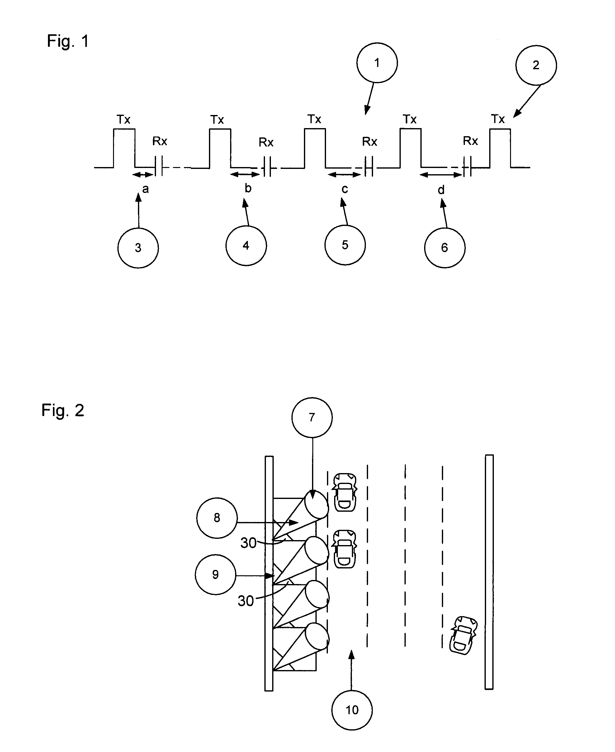
[0051]A true time-of-flight radar essentially transmits a pulse of a radio frequency carrier wave using a transmit antenna and then waits for a receive echo and measures the time between the transmit (Tx) ...


PUM


Abstract

A method of using a directional sensor for the purposes of detecting the presence of a vehicle or an object within a zone of interest on a roadway or in a parking space. The method comprises the following steps: transmitting a microwave transmit pulse of less than 5 feet; radiating the transmitted pulse by a directional antenna system; receiving received pulses by an adjustable receive window; integrating or combining signals from multiple received pulses; amplifying and filtering the integrated receive signal; digitizing the combined signal; comparing the digitized signal to at least one preset or dynamically computed threshold values to determine the presence or absence of an object in the field of view of the sensor; and providing at least one pulse generator with rise and fall times of less than 3 ns each and capable of generating pulses less than 10 ns in duration.

Description

CROSS-REFERENCE TO RELATED APPLICATIONS[0001]This application is a continuation of U.S. patent application Ser. No. 13 / 464,706 filed May 4, 2012, which claims priority to and the benefit of U.S. Provisional Application Ser. Nos. 61 / 549,029 filed Oct. 19, 2011 and 61 / 638,173 filed Apr. 25, 2012. The disclosures of these priority applications are hereby incorporated herein by reference in their entirety.FIELD OF THE INVENTION[0002]What is described is a directional speed and distance measurement sensor based on a time of flight ranging technique that can be used to detect objects in a zone of interest such as automobiles near an intersection stop bar, access control device, or a parking space. The sensor can also act as a transponder and can be combined with in-vehicle devices and other transponders and can be deployed as a network.BACKGROUND OF THE INVENTION[0003]The use of time-of-flight technology in the field of slow moving vehicles or persons in a narrow and defined zone of inter...

Claims


Application Information

Patent Timeline
Patent Type & Authority Patents(United States)
IPC IPC(8): G01S13/00G01S7/40G08G1/01G01S13/931
CPCG01S2013/9339G01S13/931G01S2013/936G01S7/40G01S2013/9314G01S13/00G01S13/12G01S7/2926G01S7/2927B60Q9/002G08G1/09G01S2013/9316G01S2013/9329G01S13/10G01S13/91G01S13/02G01S13/103G01S13/14G01S13/32G01S7/003G07C1/30G08G1/14
Inventor SUBRAMANYA, BALU
Owner SUBRAMANYA BALU
Why Eureka
Try Eureka