Plating apparatus and plating method for forming magnetic film

a technology of magnetic film and plating apparatus, which is applied in the direction of centrifuges, separation processes, electrolysis components, etc., can solve the problems of poor bubble escape, large footprint of plating apparatus, and general difficulty in automation of apparatus, etc., and achieves the effect of wide footprin

Inactive Publication Date: 2014-11-04
EBARA CORP
View PDF25 Cites 0 Cited by
  • Summary
  • Abstract
  • Description
  • Claims
  • Application Information

AI Technical Summary

Benefits of technology

[0008]The present invention has been made in view of the above situation. It is therefore an object of the present invention to provide a magnetic film plating apparatus and method which employs a dip method that allows relatively good escape of bubbles and does not require a wide footprint and which, even when a ferromagnetic material is used for an anode, can form a magnetic film on a substrate surface while minimizing the influence of the anode on the uniformity of magnetic anisotropy in the magnetic film.
[0040]According to the present invention, a dip method, which does not require a wide footprint, can be employed and, even when a ferromagnetic material is used for an anode, a magnetic film having magnetic anisotropy can be formed on a substrate surface while minimizing the influence of the anode on the uniformity of the magnetic anisotropy.

Problems solved by technology

In the case where a magnetic film is formed by electroplating on a surface (surface to be plated) of a substrate which is held horizontally with the surface facing downwardly and immersed in a plating solution in a plating tank, however, escape of bubbles is generally poor.
In addition, such a plating apparatus needs a wide footprint and automation of the apparatus is generally difficult.
When using a ferromagnetic material for an anode and forming a magnetic film on a surface (surface to be plated) of a substrate by electroplating while forming a magnetic field around the substrate, due to the presence of the anode of ferromagnetic material, magnetic field lines will deviate from a reference direction by a certain angle, making it difficult to equalize the magnetic density in the substrate surface.
Such non-uniformity of the magnetic density in the substrate surface affects uniformity of the magnetic anisotropy in the magnetic film formed on the substrate.

Method used


Image

  • Plating apparatus and plating method for forming magnetic film
  • Plating apparatus and plating method for forming magnetic film
  • Plating apparatus and plating method for forming magnetic film

Examples


Embodiment Construction

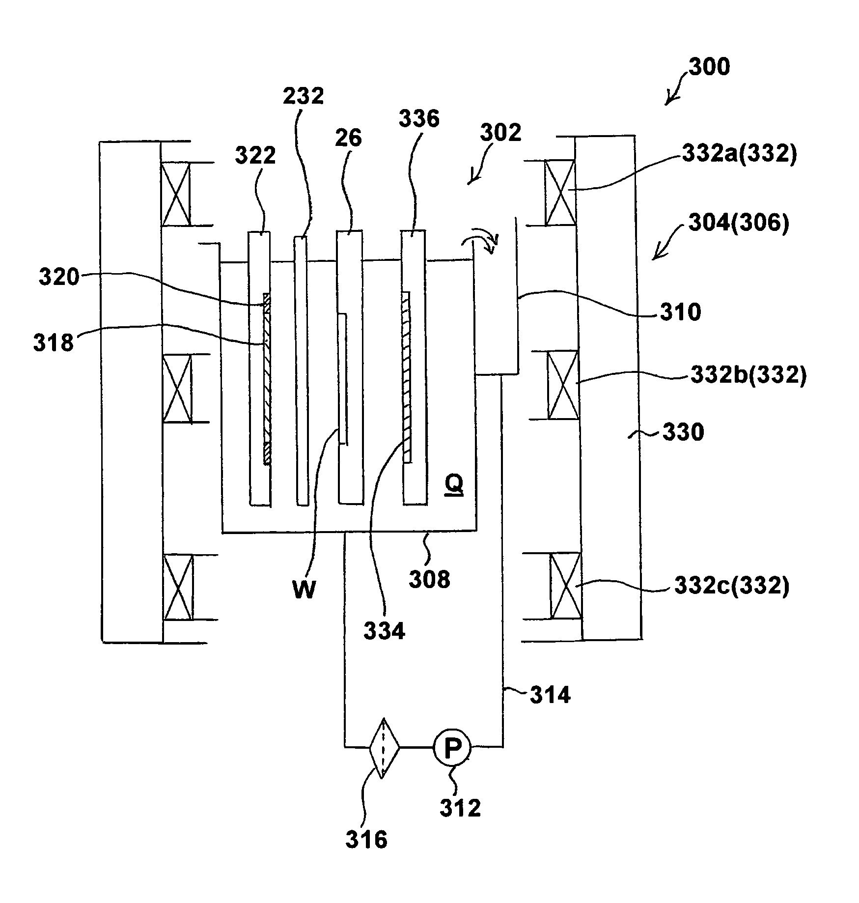
[0064]Preferred embodiments of the present invention will now be described with reference to the drawings. In the following embodiments, a magnetic film of permalloy (Ni / Fe=80 / 20%) is formed on a surface (surface to be plated) of a substrate, such as a semiconductor wafer. A plating solution capable of forming permalloy is used. An anode of nickel (Ni), which is a ferromagnetic material, or an insoluble anode (e.g., Ti coated with IrO2 or Ti cladded with 1-μm Pt) may be used. Besides a permalloy magnetic film, a magnetic film of cobalt or a cobalt alloy, for example, can also be formed.

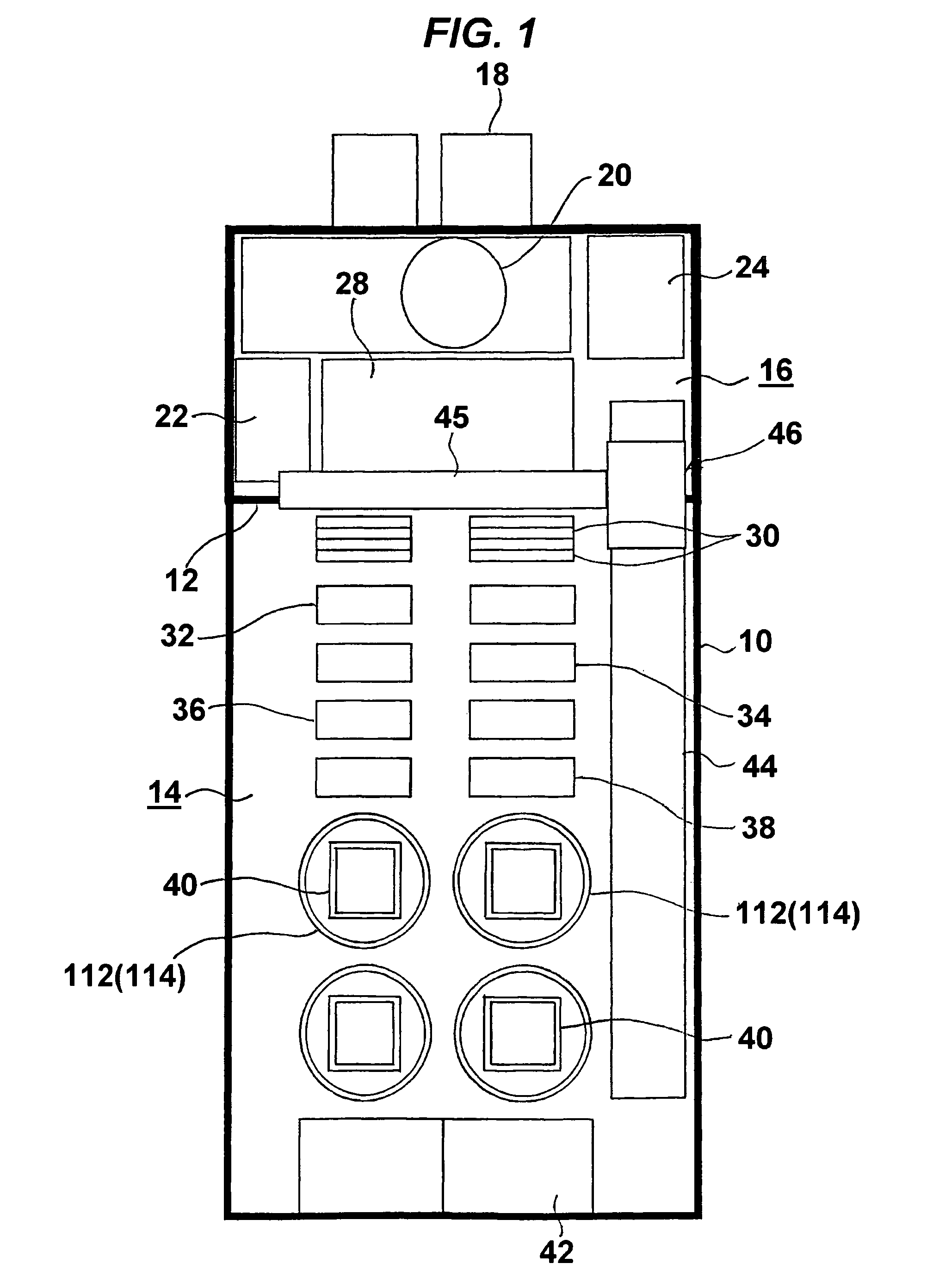
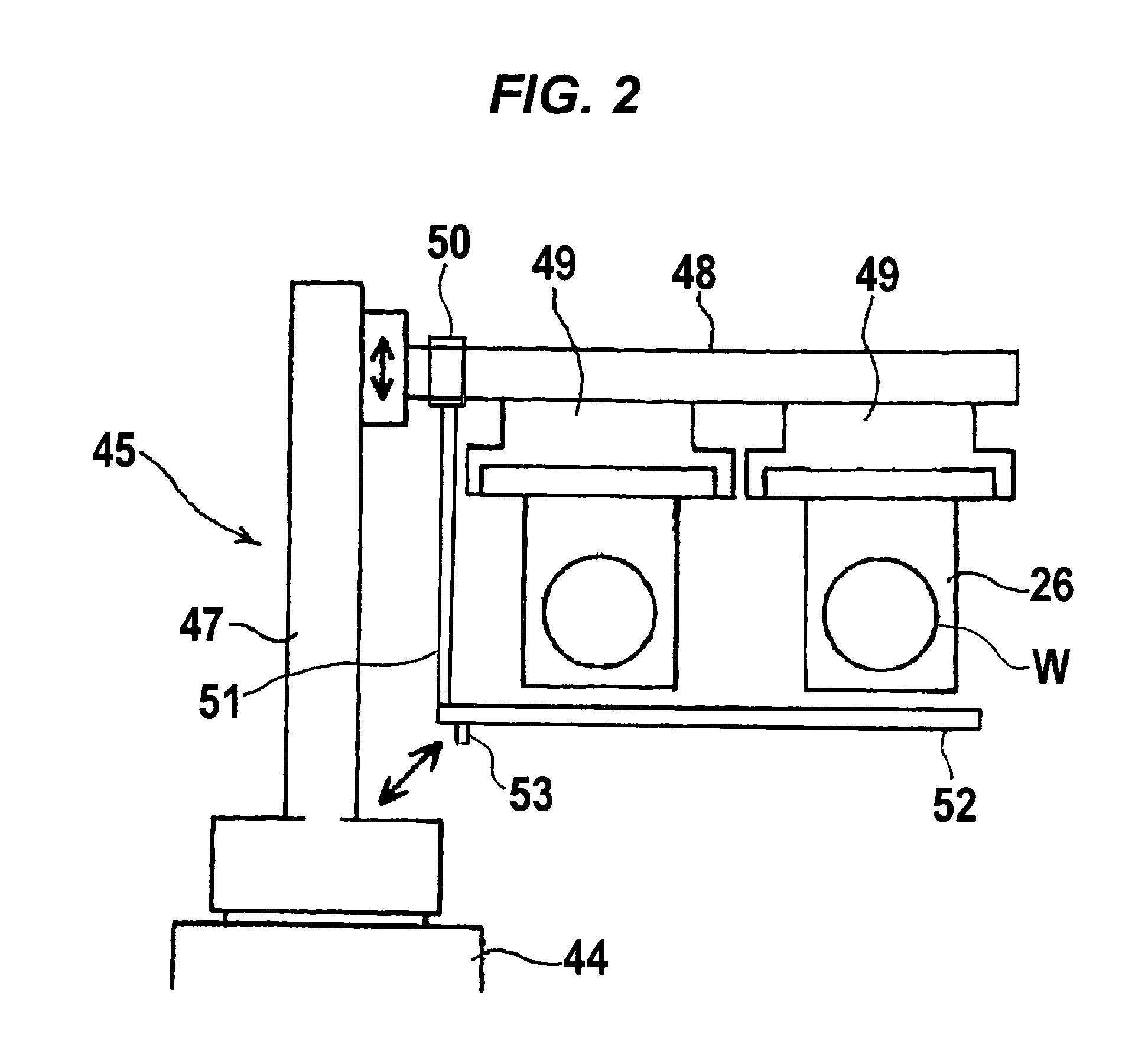
[0065]FIG. 1 shows an overall layout plan of a plating facility according to an embodiment of the present invention. This plating facility performs the whole plating process for a substrate, including pre-plating treatment, plating and post-plating treatment, automatically in a successive manner. The plating facility includes a main frame 10 with a face panel attached thereto. The interior of the main...


PUM

PropertyMeasurementUnit
thicknessaaaaaaaaaa
movement velocityaaaaaaaaaa

Abstract

A magnetic film plating apparatus employs a dip method that allows relatively good escape of bubbles and does not require a wide footprint and, even when a ferromagnetic material is used for an anode, can form a magnetic film on a substrate surface while minimizing the influence of the anode on the uniformity of magnetic anisotropy in the magnetic film. The magnetic film plating apparatus includes a plating tank for holding a plating solution, an anode vertically disposed in the plating tank at a position to be immersed in the plating solution, a substrate holder for holding a substrate W and positioning the substrate W opposite the anode, and a magnetic field generator, disposed outside the plating tank, for generating a magnetic field around the substrate W held by the substrate holder and positioned opposite the anode.

Description

BACKGROUND OF THE INVENTION[0001]1. Field of the Invention[0002]The present invention relates to a magnetic film plating apparatus and method, and more particularly to a magnetic film plating apparatus and method which is useful for forming a magnetic film on an exposed surface of a metal layer formed on a surface of a substrate, such as a semiconductor wafer.[0003]2. Description of the Related Art[0004]As a technique for forming a magnetic film on a device, such as an MRAM or a magnetic head, by electroplating, a method is known, for example, which comprises immersing a substrate, which is held in a horizontal position with a surface to be plated (front surface) of the substrate facing downwardly, in a plating solution in a plating tank, and passing a plating current between the substrate and an anode disposed parallel to the substrate while forming a horizontal magnetic field around the substrate by means of electromagnets (or permanent magnets) disposed on opposite sides of the p...

Claims


Application Information

Patent Timeline
Patent Type & Authority Patents(United States)
IPC IPC(8): C25D17/12C25D17/00C25D5/00
CPCC25D17/001C25D5/006C25D17/00C25D17/12C25D5/009
Inventor ENDO, YASUHIKOKURIYAMA, FUMIOKIMURA, MASAAKI
Owner EBARA CORP
Why Eureka
Try Eureka