Ultrasonic sealing jaw and method for ultrasonic sealing

a sealing jaw and ultrasonic technology, applied in the direction of lamination, paper/cardboard containers, containers, etc., can solve the problems of increasing difficulty in finding a window of process parameters that produces an overall satisfactory tube seal when using known sealing jaws/processes, and may still arise problems

Inactive Publication Date: 2014-11-11
3L LUDVIGSEN
View PDF15 Cites 1 Cited by
  • Summary
  • Abstract
  • Description
  • Claims
  • Application Information

AI Technical Summary

Benefits of technology

[0013]The recess in the film-film welding portion of the sealing jaw is configured to reduce the pressure exerted by the sealing jaw in a proximal region of the film-film welding portion next to the film-tube welding portion as compared to the pressure exerted by a distal region of the film-film welding portion, the distal portion being located adjacent to the proximal region and extending away from the film-tube welding portion.
[0070]Surprisingly, by reducing the pressure exerted on the plastic film by the film-film welding portion in a region along an edge towards the film-tube welding portion or at least partially along the edge, the sealing performance of the process is improved considerably in particular in the region of the transition from the film-to-film surface joint / attachment to the film-to-tube attachment. Thereby, a larger window for viable process parameters providing satisfactory tube seals is obtained, resulting in a less critical process that is more stable and versatile, e.g. with respect to different film / tube material combinations.

Problems solved by technology

In practice it has proved difficult to obtain a liquid-tight connection between the outer face of the tube and the plastic films in the two transition areas in which the outer face of the tube and the two plastic films meet.
A further challenge is aligning the seal around the tube with a given feature on the plastic film so as to form a liquid proof connection between the tube seal and the given feature.
Such further process specifications / constraints / requirements that have to be fulfilled by the tube sealing makes it increasingly difficult to find a window of process parameters that produces an overall satisfactory tube seal when using known sealing jaws / processes.
Despite the improvements achieved by the method and apparatus according to EP 1 677 966 B1, problems may still arise in the above-mentioned transition areas, in particular when trying to satisfy the further constraints of the tube welding process, i.e. provide satisfactory results for welding the plastic films together and / or sealing the plastic films to the tube and / or aligning the tube seal with given features.
The problem of simultaneously satisfying the process constraints for the film-to-film attachment, the film-to-tube attachment and for the transition areas in one ultrasonic process becomes even more pronounced for thin plastic films with a thickness well below 0.15 mm.
Problems observed in practice include excessive hardening of the film, burning and cutting of the film, unsatisfactory attachment of the film to the tube, and leaks particularly along the tube in the two transition areas in which the outer face of the tube and the two plastic films meet.
Such a sealing process thus requires at least a partial melting of the tube material and has the disadvantage of imposing narrow restrictions on the choice of process compatible tube / film materials.
This adds to process complexity and cost.

Method used


Image

  • Ultrasonic sealing jaw and method for ultrasonic sealing
  • Ultrasonic sealing jaw and method for ultrasonic sealing
  • Ultrasonic sealing jaw and method for ultrasonic sealing

Examples


Embodiment Construction

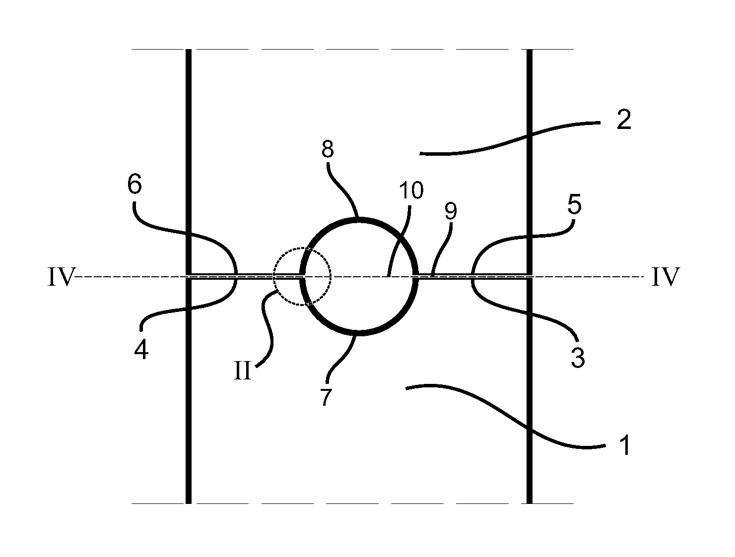
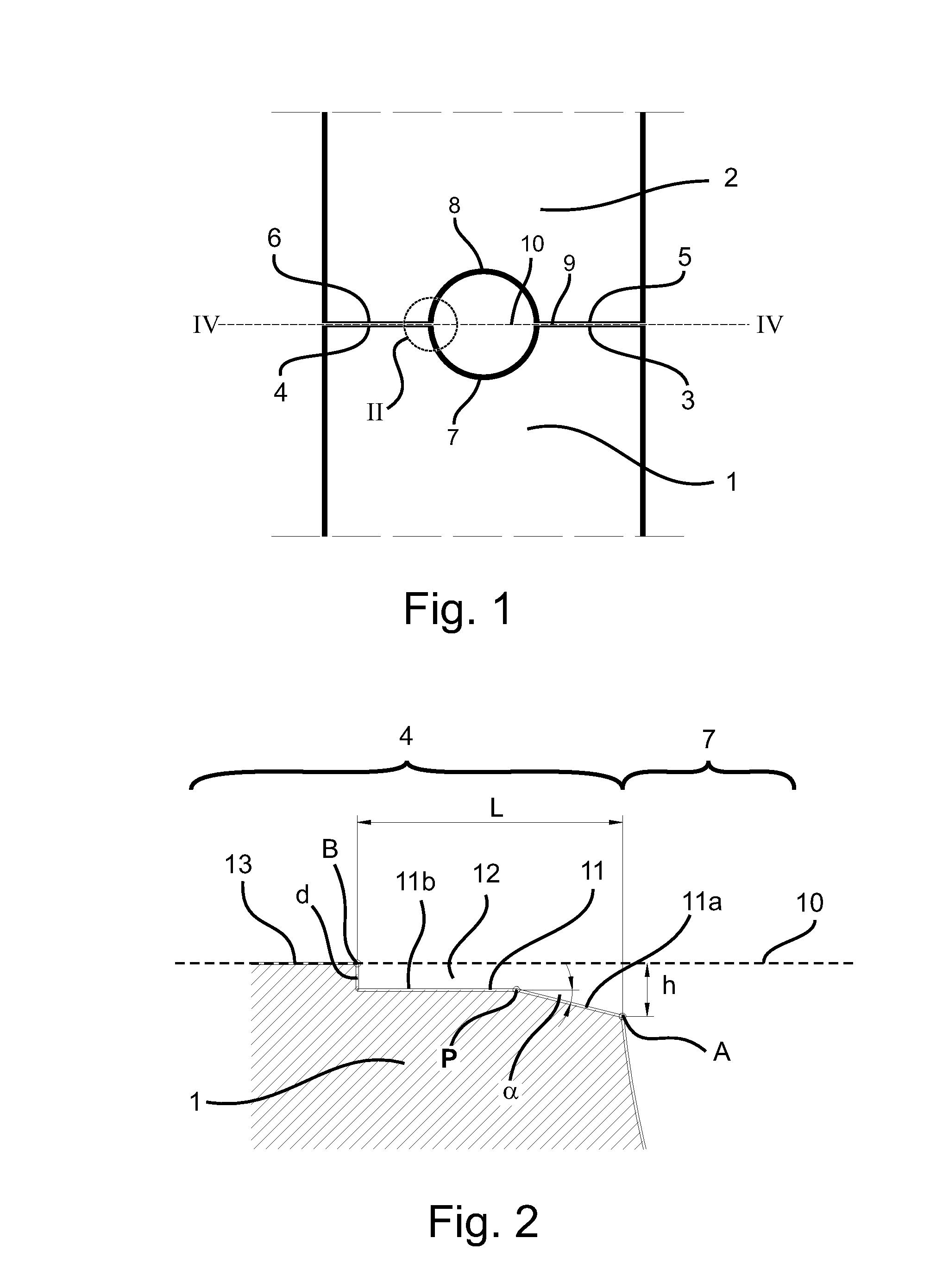
[0084]FIG. 1 shows two cooperating sealing jaws 1, 2 each having two film-film welding portions 3, 4 and 5, 6, respectively, and film-tube welding portions 7, 8 of substantially semi-circular cross-section. The two sealing jaws meet at a joint face 9. In the absence of tube or films the most elevated regions of the film-film welding portions 3, 4 and 5, 6 of the ultrasonic sealing jaws 1, 2 contact each other at the joint face 9. The most elevated regions of the film-film welding portions 3, 4, 5, 6 also define the top plane of the respective sealing jaw 1, 2.

[0085]In combination, the film-tube welding portions 7, 8 of the cooperating sealing jaws form a cavity for receiving the tube arranged between portions of plastic film, and the film-film welding portions 3, 4 and 5, 6 embrace the portions of plastic film. The embodiment shown in FIG. 1 provides a cavity of substantially circular cross-section for receiving the tube arranged between portions of plastic film.

[0086]Circle II indi...


PUM

PropertyMeasurementUnit
angleaaaaaaaaaa
angleaaaaaaaaaa
angleaaaaaaaaaa

Abstract

An ultrasonic sealing jaw (1) is used for sealing portions of plastic film to a tube so as to form a sealing engagement of the portions of plastic film around the circumference of the tube. The sealing jaw (1) includes a concave film-tube welding portion (7) for receiving the tube covered by the plastic films the film-tube welding portion (7) to form the film-tube attachment. Adjacent to at least one side of the film-tube welding portion (7) of the sealing jaw (1), is a substantially flat film-film welding portion (3, 4) for engaging the plastic film and sealing adjacent portions of plastic film to each other in an area adjoining the tube. A film-film welding portion (3, 4) defining a top plane (10) of the sealing jaw (1) has at least one recess with a surface (11) so as to form a cavity (12) and forms a cavity (12) with an opening towards the film-tube welding portion (7).

Description

[0001]This is a National Phase Application filed under 35 U.S.C. 371 as a national stage of PCT / DK2010 / 050144, filed Jun. 16, 2010, and claiming the benefit from European Application No. 09162946.9, filed Jun. 17, 2009, the content of which is hereby incorporated by reference in its entirety.TECHNICAL FIELD[0002]The invention relates to an ultrasonic sealing jaw according to the preamble of claim 1 and a method for ultrasonic sealing according to the preamble of claim 15.[0003]The invention relates to an ultrasonic sealing jaw for sealing portions of plastic film to a tube so as to form a sealing engagement of the portions of plastic film around the circumference of the tube, the sealing jaw comprising a concave film-tube welding portion for receiving the tube covered by the plastic films the film-tube welding portion being adapted to form the film-tube attachment, and, adjacent to at least one side of the concave portion of the sealing jaw, a substantially flat film-film welding po...

Claims


Application Information

Patent Timeline
Patent Type & Authority Patents(United States)
IPC IPC(8): B32B37/00B29L31/00B31B19/84A61J1/14A61J1/10B29C65/08B31B19/64B29C65/00
CPCB29C66/81417B29C66/53262B29C66/80B29C65/088B29C66/83221B29C66/92611A61J1/10B29C66/81422B31B19/64B29C66/1122B29C66/326B29C66/242B29C66/81419B29C66/3452B29C65/08B31B19/84B29C66/53263B29C66/81431A61J1/1475B29K2995/0069B29C66/81427B29C66/9512B29C66/346B29C66/344B29C66/81433B29C66/81423B29C66/92B31B2219/9054B29C66/929B29C66/81425B29L2031/7148B31B2219/6038B29C66/9513B31B70/642B31B70/844B29C66/133B29C66/72321
Inventor BANG, MOGENS MOLLERSIMMELSGAARD, PETER ASTRUP
Owner 3L LUDVIGSEN
Why Eureka
Try Eureka