Current-sense resistor

a current-sense resistor and resistor technology, applied in resistors, non-adjustable resistors, base elements, etc., can solve the problems of increasing the temperature constancy of current-sense resistors, and the favorable effect of current measurement temperature stability, so as to reduce the temperature dependence of measurement

Active Publication Date: 2014-11-11
ISABELLENHUTTE HEUSLER
View PDF18 Cites 9 Cited by
  • Summary
  • Abstract
  • Description
  • Claims
  • Application Information

AI Technical Summary

Benefits of technology

[0014]With such design of the current-sense resistor according to the invention with two voltage contacts, there is a preference for at least one incision in each of both associated plate-shaped connecting parts in order to reduce temperature dependency of the measurement.
[0015]Here, both incisions in both plate-shaped connecting parts are preferably arranged in such a way as to transform the current lines and the equipotential lines in the plate-shaped connecting parts in such a way that the equipotential lines in the plate-shaped connecting parts running through the voltage contacts directly reach the contact point (joining point) with the resistance element, i.e. usually the weld seam between the plate-shaped connecting parts and the resistance element. The advantage of this is that the voltage contacts are then at the same electrical potential as the edges of the resistance element, so that the voltage measurement is not in the least distorted by the conductor material of the plate-shaped connecting parts.

Problems solved by technology

However, the demands on temperature constancy of such current-sense resistors are still increasing.
Here, the incision in the connecting parts runs parallel to the current flow direction between both connecting parts and therefore does not have a particularly favorable effect on the temperature stability of the current measurement.

Method used


Image

  • Current-sense resistor
  • Current-sense resistor
  • Current-sense resistor

Examples


Embodiment Construction

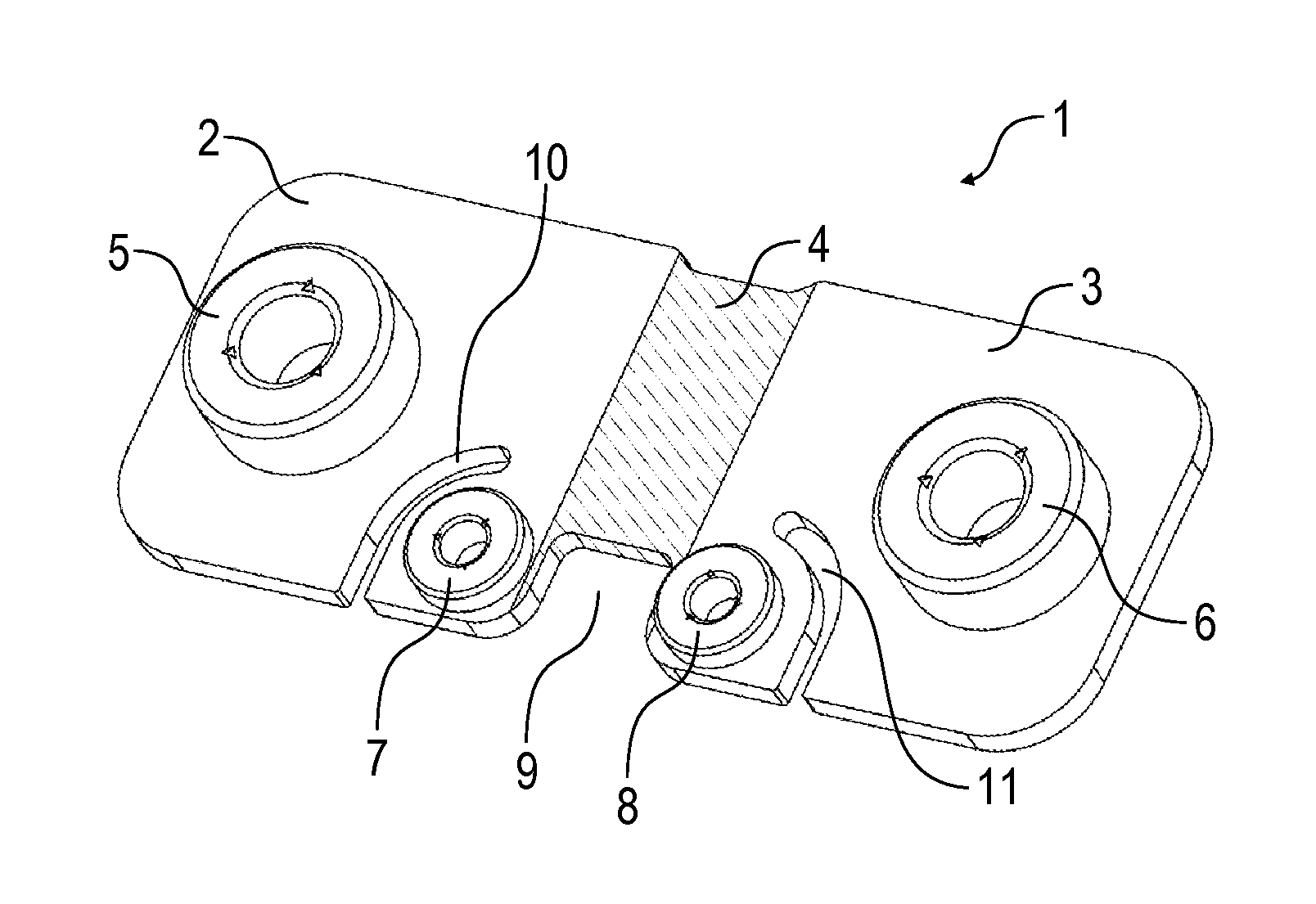
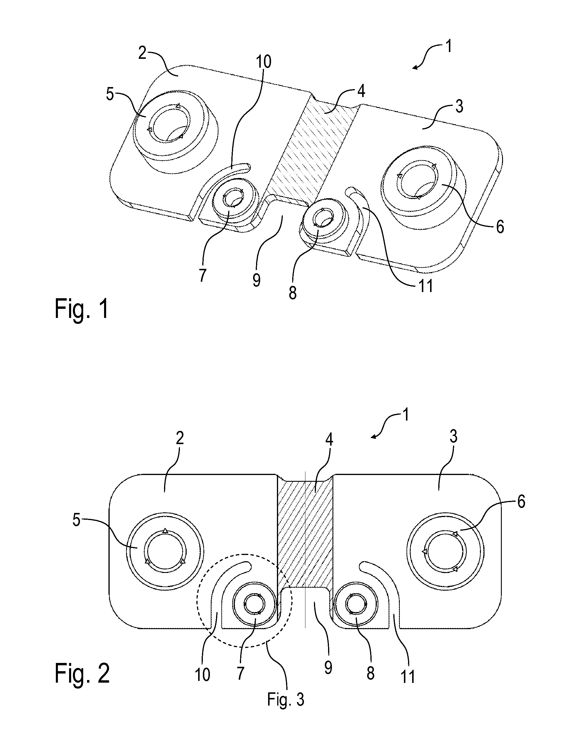
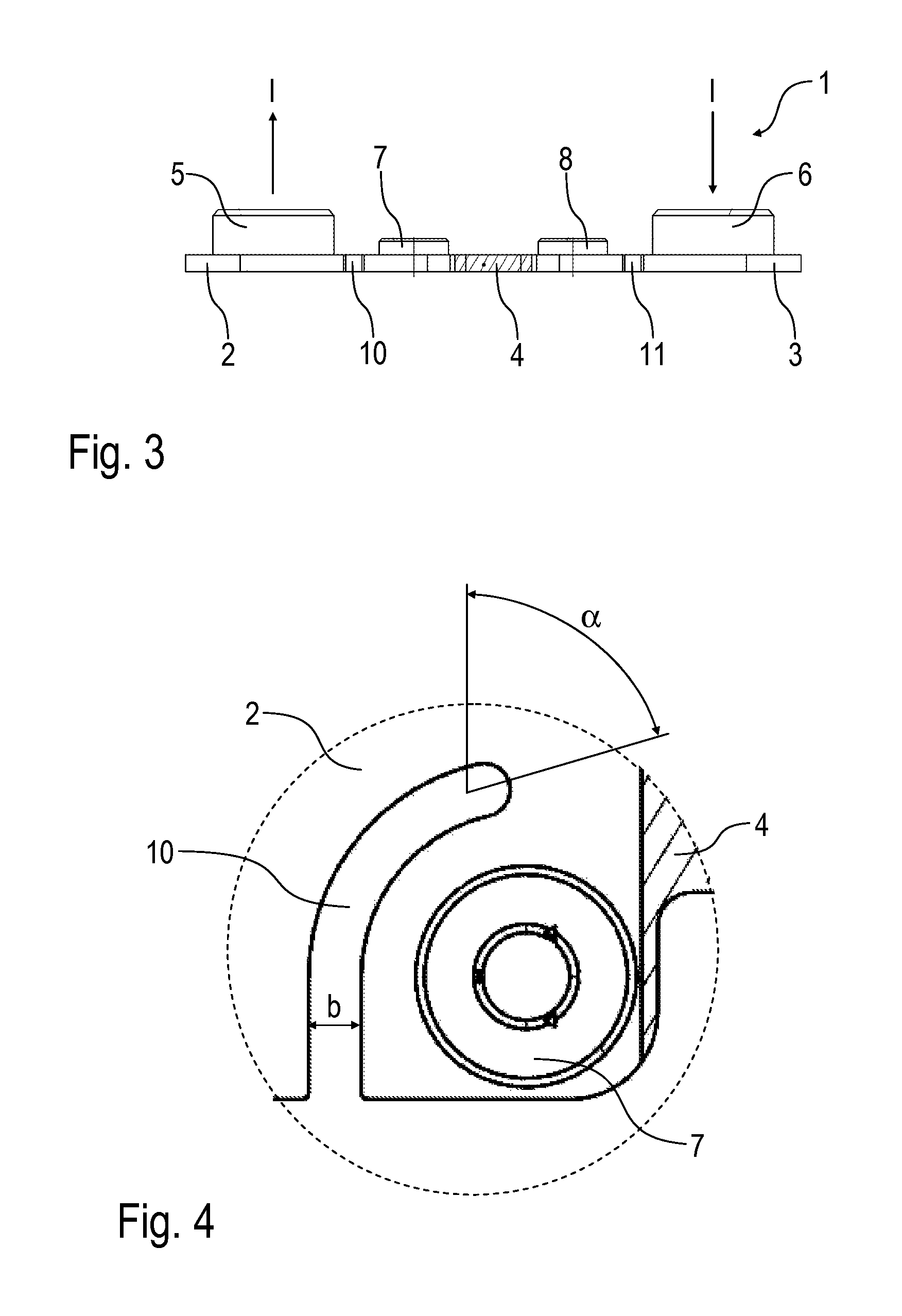
[0006]The invention is based on the technical-physical finding that the conductor material (e.g. copper) of the plate-shaped connecting parts has a much higher temperature coefficient than the resistance material (e.g. Cu84Ni4Mn12) of the plate-shaped resistance element. During the measuring of the electrical current that drops over the resistance element between both voltage contacts, there is, however, also an influence on the measurement caused by the material of the connecting parts. The temperature dependency of the voltage measurement thus is not only determined by the temperature coefficient of the resistance material, but also by the temperature coefficient of the conductor material. Here, it is important to take into consideration that the temperature coefficient of copper, for example, is α=83.9·10−3 K−1 and thus greater by a factor of 195 than the temperature coefficient of Cu84Ni4Mn12 (Manganin®) with α=0.02·10−3 K−1. Due to the much greater temperature coefficient of co...


PUM


Abstract

The invention relates to a current-sensing resistor (1) for measuring an electric current, in particular also for measuring a battery current in a vehicle power supply, having a plate-shaped first connecting part (3) for introducing the electrical current to be measured, wherein the plate-shaped first connecting part (3) consists of an electrically conductive conductor material; a plate-shaped second connecting part (2) for conducting away the electrical current to be measured, wherein the plate-shaped second connecting part (2) consists of an electrically conductive conductor material; and a plate-shaped resistance element (4), which is connected in the current path between the two connecting parts and through which the electrical current to be measured flows, wherein the resistance element (4) consists of a comparatively high-impedance resistance material. According to the invention an incision (10, 11) is arranged in the plate-shaped first connecting part (3) and/or in the plate-shaped second connecting part (2) in order to reduce the temperature dependency of the measurement and to eliminate the influence of the plate-shaped connecting parts (usually copper or aluminum).

Description

BACKGROUND OF THE INVENTION[0001]The invention concerns a current-sense resistor for measuring an electrical current, especially for measuring a battery current in a motor vehicle on-board electrical system.[0002]EP 0 605 800 A1 discloses a current-sense resistor of this type, which consists of two copper plate-shaped connecting parts and an also plate-shaped low-ohm resistance element made of a resistance alloy (e.g. Cu84Ni4Mn12), wherein the resistance element is placed between the connecting parts and welded to the connecting parts. Such current-sense resistors are used to measure the electrical current as per the well-known four-wire technology, wherein the current to be measured is conducted through the resistance element via the plate-shaped connecting parts. The voltage drop over the resistance element then forms a measure for the electrical current to be measured in accordance with Ohm's law. The known current-sense resistor consequently has two voltage contacts on both plat...

Claims


Application Information

Patent Timeline
Patent Type & Authority Patents(United States)
IPC IPC(8): G01R1/20H01C7/06H01C7/00
CPCH01C7/06H01C7/001G01R1/203H01C7/00G01R19/00
Inventor HETZLER, ULLRICH
Owner ISABELLENHUTTE HEUSLER
Why Eureka
Try Eureka