Gyro sensor and sensor apparatus using same

a sensor and gyro technology, applied in the field of gyro sensors, can solve the problems of large variable detection value, and achieve the effects of reducing temperature dependence of detection value, reducing sensitivity to angular velocity, and less susceptibl

Inactive Publication Date: 2009-02-03
MATSUSHITA ELECTRIC WORKS LTD
View PDF14 Cites 17 Cited by
  • Summary
  • Abstract
  • Description
  • Claims
  • Application Information

AI Technical Summary

Benefits of technology

[0009]According to the above gyro sensor, the detection spring which fixes the detection mass body and the driven mass body to the support base plate is disposed to extend from the detection mass body in only one direction so as to support the detection mass body in a cantilever manner. Thus, even if the primary base plate and the support base plate are different in thermal expansion coefficient, almost no thermal stress will act on the primary base plate, and thereby the gyro sensor will have almost no change in resonance frequency. This makes it possible to provide a lowered temperature dependence of a detection value.
[0063]According to the present invention, the detection spring which fixes the detection mass body and the driven mass body to the support base plate is disposed to extend from the detection mass body in only one direction so as to support the detection mass body in a cantilever manner. Thus, even if the primary base plate and the support base plate are different in thermal expansion coefficient, almost no thermal stress will act on the primary base plate, and thereby the gyro sensor will have almost no change in resonance frequency. This provides an advantage of being able to achieve a lowered temperature dependence of a detection value.

Problems solved by technology

The change in resonance frequency of the gyro sensor inevitably causes variation in detection value.
Therefore, the gyro sensor disclosed in the Japanese Patent Laid-Open Publication No. 2003-194545 involves a problem about a relatively large temperature dependence of a detection value.

Method used


Image

  • Gyro sensor and sensor apparatus using same
  • Gyro sensor and sensor apparatus using same
  • Gyro sensor and sensor apparatus using same

Examples


first embodiment

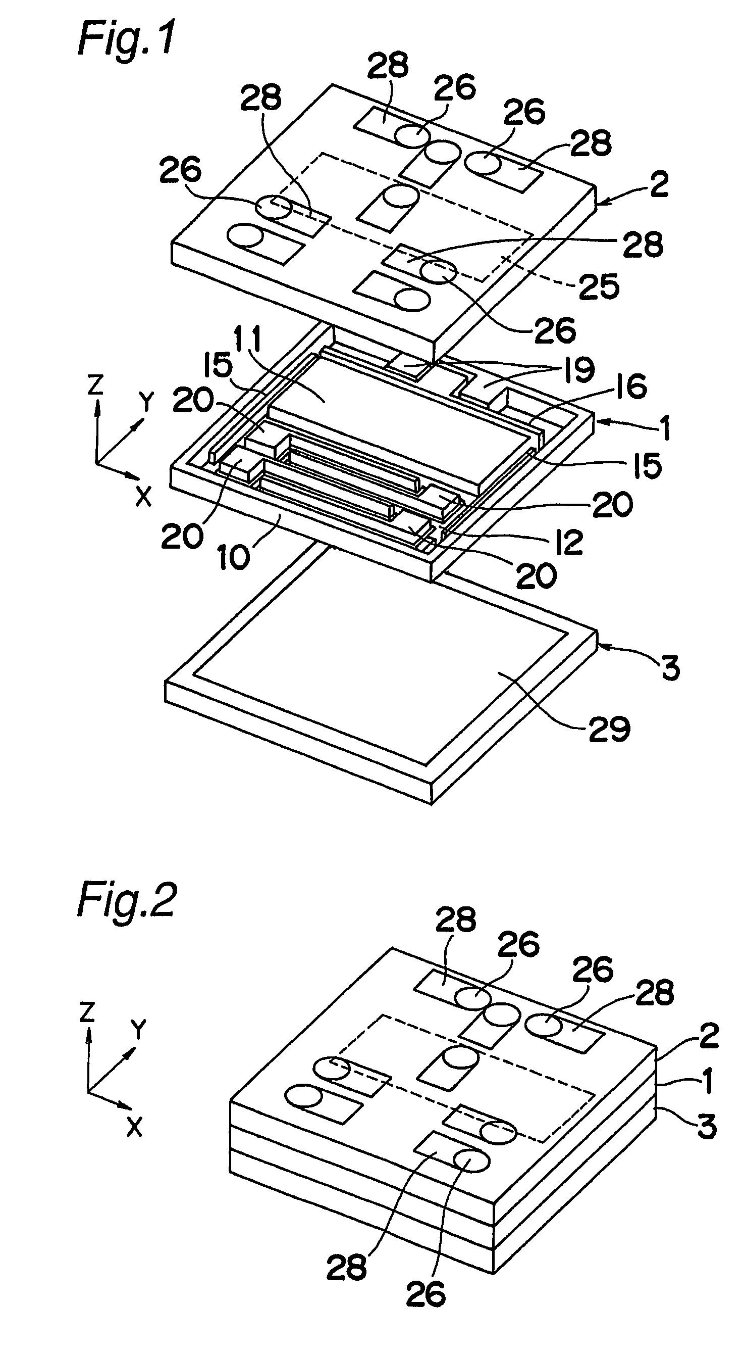
[0101]As shown in FIGS. 1 and 2, a gyro sensor according to a first embodiment of the present invention has a three-layer structure comprising a primary base plate 1 formed of a silicon substrate, a support base plate 2 formed of a glass substrate and superimposed on one surface of the primary base plate 1, and a cap 3 formed of a glass substrate superimposed on the other surface of the primary base plate 1. Each of the support base plate 2 and the cap 3 is joined to the primary base plate 1, for example, by an anodic bonding process. The primary base plate 1 may be made using any suitable semiconductor material other than silicon.

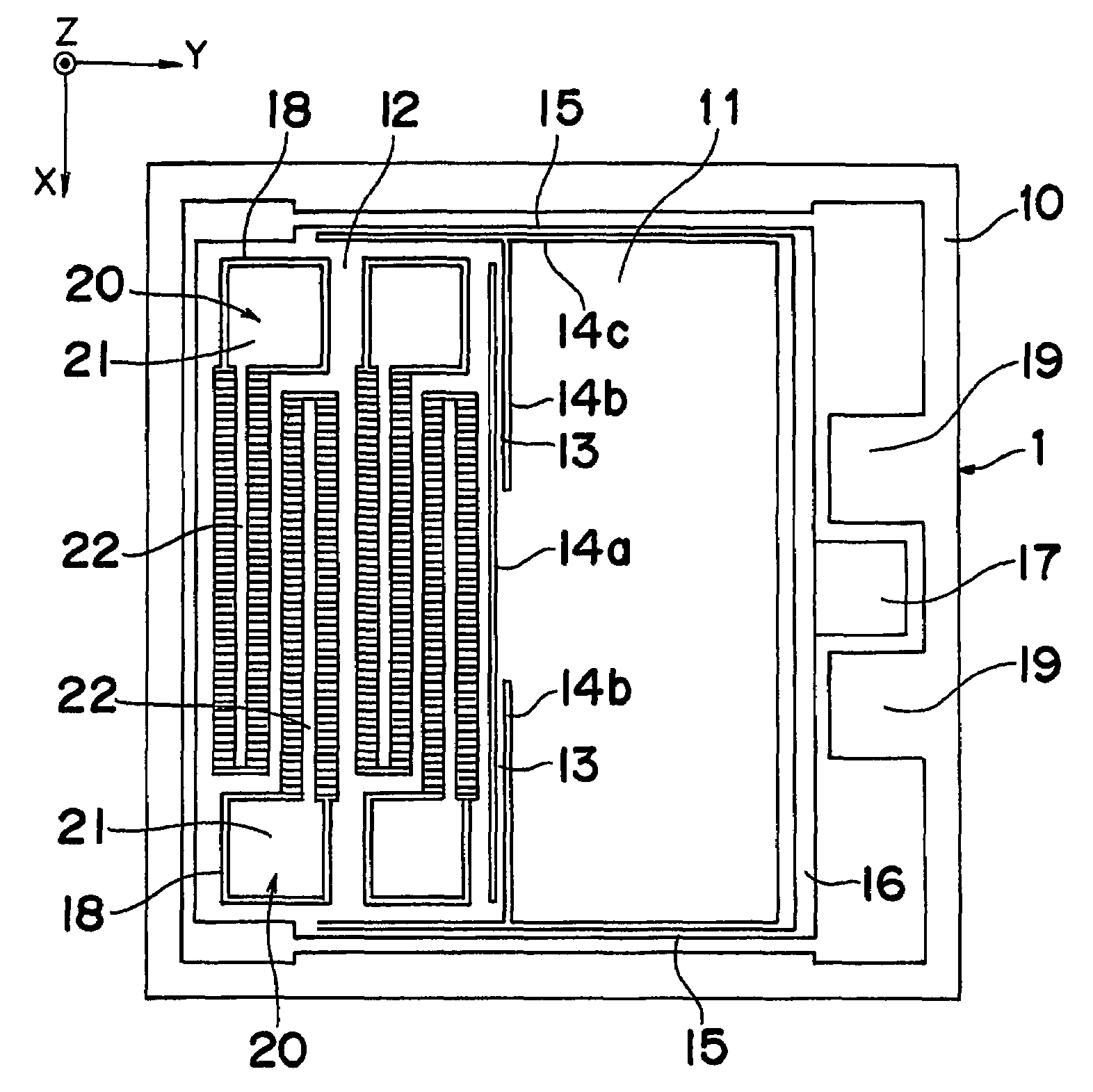
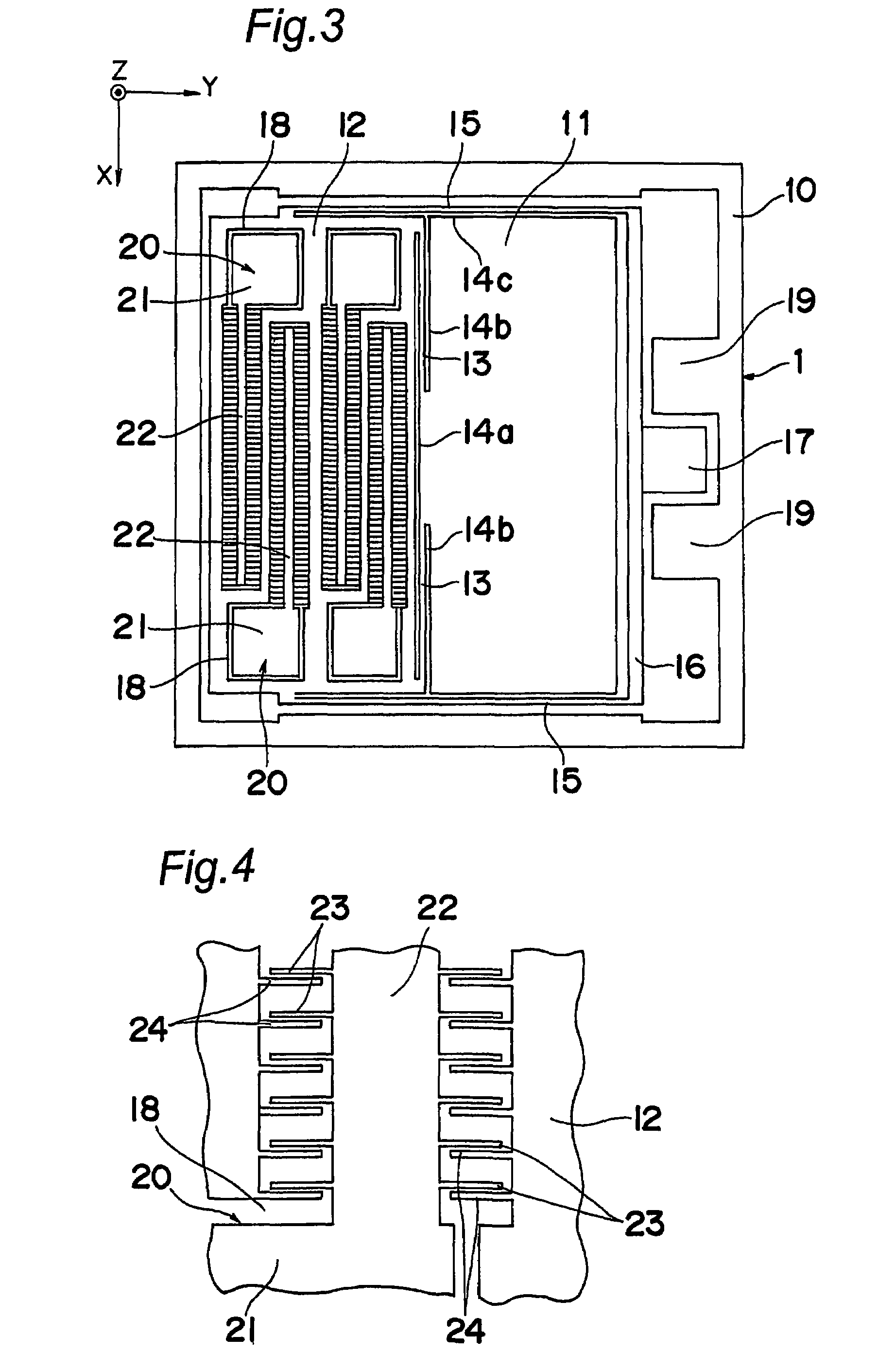
[0102]As shown in FIG. 3, the primary base plate 1 includes a driven mass body 11 and a detection mass body 12 which are formed in a rectangular shape in top plan view and disposed in parallel to one another along a plate surface of the primary base plate 1. The primary base plate 1 further includes a rectangular-shaped frame 10 surrounding around the driv...

second embodiment

[0121]As shown in FIG. 9, a gyro sensor A according to the second embodiment comprises a connection segment 35 separated from a frame 10, in place of the lower ground segment 19 illustrated in FIG. 3 in the gyro sensor A according to the first embodiment. A connection pad 36 is formed on a surface region of the connection segment 35 opposed to the corresponding through-hole 26. While omitted in the figures for the first embodiment, the connection pad 36 is also formed on each of the fixing segment 17, the ground segment 19 and the electrode segments 21. The through-hole 26 is formed in the support base plate 2 in each of regions thereof corresponding to the connection pads 36.

[0122]The shape of a stationary driving electrode 25 in the second embodiment will be described with reference to FIG. 12A showing a support base plate 2 in a third embodiment. The stationary driving electrode 25 in the second embodiment includes a stationary-driving-electrode pad 37 extending rightwardly (in F...

third embodiment

[0126]As shown in FIG. 12A, a gyro sensor A according to a third embodiment of the present invention comprises a support base plate 2 formed with a stress relaxation groove 38 having a strip-shaped opening elongated in the X-direction. The stress relaxation groove 38 is formed in a region of the support base plate 2 opposed to a detection mass body 12.

[0127]The stress relaxation groove 38 may penetrate through the support base plate 2 in its thickness direction as shown in FIG. 12B, or may not penetrate therethrough as shown in FIG. 12C. A technique for forming the stress relaxation groove 38 may include a reactive ion etching process, and a wet etching using hydrofluoric acid. According to the gyro sensor according to the third embodiment, even if the support base plate 2 and a primary base plate are different in thermal expansion coefficient, a thermal stress generated in the width direction of the stress relaxation groove 38 (Y-direction) is relaxed by the change in width dimensi...


PUM


Abstract

Disclosed is a gyro sensor, which comprises a primary base plate (1) and a support base plate (2) which are superimposed on one another. The primary base plate (1) is provided with a driven mass body (11) to be driven in such a manner as to be vibrated in a direction intersecting with a surface of the support base plate (2), and a detection mass body (12) coupled with the driven mass body (11) through a drive spring (13) and adapted to be displaceable in a plane along the support base plate (2). Two detection springs (15) extending in the arranging direction of the driven mass body (11) and the detection mass body (12) are connected, respectively, to opposite side of the detection mass body (12), and the other ends of the detection springs (15) are connected together through a coupling segment (16). A fixing segment (17) provided at a longitudinally intermediate portion of the coupling segment (16) is fixed to the support base plate (2). A member formed by integrating the driven mass body (11) and the detection mass body (12) through the drive spring (13) is supported relative to the support base plate (2) by the detection springs (15) in a cantilever manner.

Description

TECHNICAL FIELD[0001]The present invention relates to a gyro sensor based on MEMS (Micro Electro Mechanical System) technologies, and a sensor apparatus using the gyro sensor.BACKGROUND ART[0002]In late years, a gyro sensor has been increasingly used in various systems and apparatuses, such as a suspension or airbag control system for automobiles, an inertial navigation system for airplanes and a blurring-correcting apparatus for cameras. This type of gyro sensor is operable, when an angular velocity due to an external force acts on a mass body which is being vibrated at a predetermined movement velocity, to measure a resulting Coriolis force so as to determine the angular velocity. Specifically, the Coriolis force is proportional to a vector product of the angular velocity caused by the external force and the movement velocity of the mass body, and thereby a value corresponding to the angular velocity can be derived from the measured Coriolis force and the known movement velocity o...

Claims


Application Information

Patent Timeline
Patent Type & Authority Patents(United States)
IPC IPC(8): G01C19/56G01P9/04G01C19/5719G01C19/5747G01C19/5762G01C19/5769
CPCG01C19/5719
Inventor TSUJI, KOJIGOUDA, KAZUOKIRIHARA, MASAONISHIJIMA, YOUICHIHYODO, SATOSHI
Owner MATSUSHITA ELECTRIC WORKS LTD
Why Eureka
Try Eureka