
Oscillator spring composition and method for fabricating an oscillator spring

a technology of oscillator spring and oscillator spring, which is applied in the direction of clockwork protection, ceramic shaping apparatus, domestic applications, etc., can solve the problems of limited knowledge of materials with limited coefficients of expansion, limited thermal expansion research for new materials, compounds or alloys, etc., and achieves precise proportion control, increased stiffness, and enhanced composites. the effect of matrix characteristics

Inactive Publication Date: 2014-11-18
CARBONTIME
View PDF15 Cites 0 Cited by
  • Summary
  • Abstract
  • Description
  • Claims
  • Application Information

AI Technical Summary

Benefits of technology

This solution simplifies and stabilizes the manufacturing process, providing precise thermal behavior control, reducing the number of industrial processes and parts required, and ensuring reliable performance of oscillator springs in precision instruments by maintaining thermal stability and minimizing elastic modulus changes.

Problems solved by technology

Up to the early twentieth century, knowledge of materials with limited coefficients of expansion was essentially limited to naturally occurring materials, elements or compounds.
This in turn led to research for new materials, compounds or alloys, which exhibited limited thermal expansion for the purpose of building measuring instruments.
The drawback of these alloys in the modern world (especially their use in balance springs for precision instruments) is their sensitivity to magnetic fields and a change from abnormal (i.e. positive) thermal evolution of elastic modulus to normal (i.e. negative) thermal evolution of elastic modulus in the ambient temperature range.
However, although a change in the sign of the thermal evolution of elastic modulus has been found, consistent manufacturing tolerance has been difficult to achieve and the resultant stiffening of the material has required further compensatory measures.

Method used


Image

  • Oscillator spring composition and method for fabricating an oscillator spring
  • Oscillator spring composition and method for fabricating an oscillator spring
  • Oscillator spring composition and method for fabricating an oscillator spring

Examples


Embodiment Construction

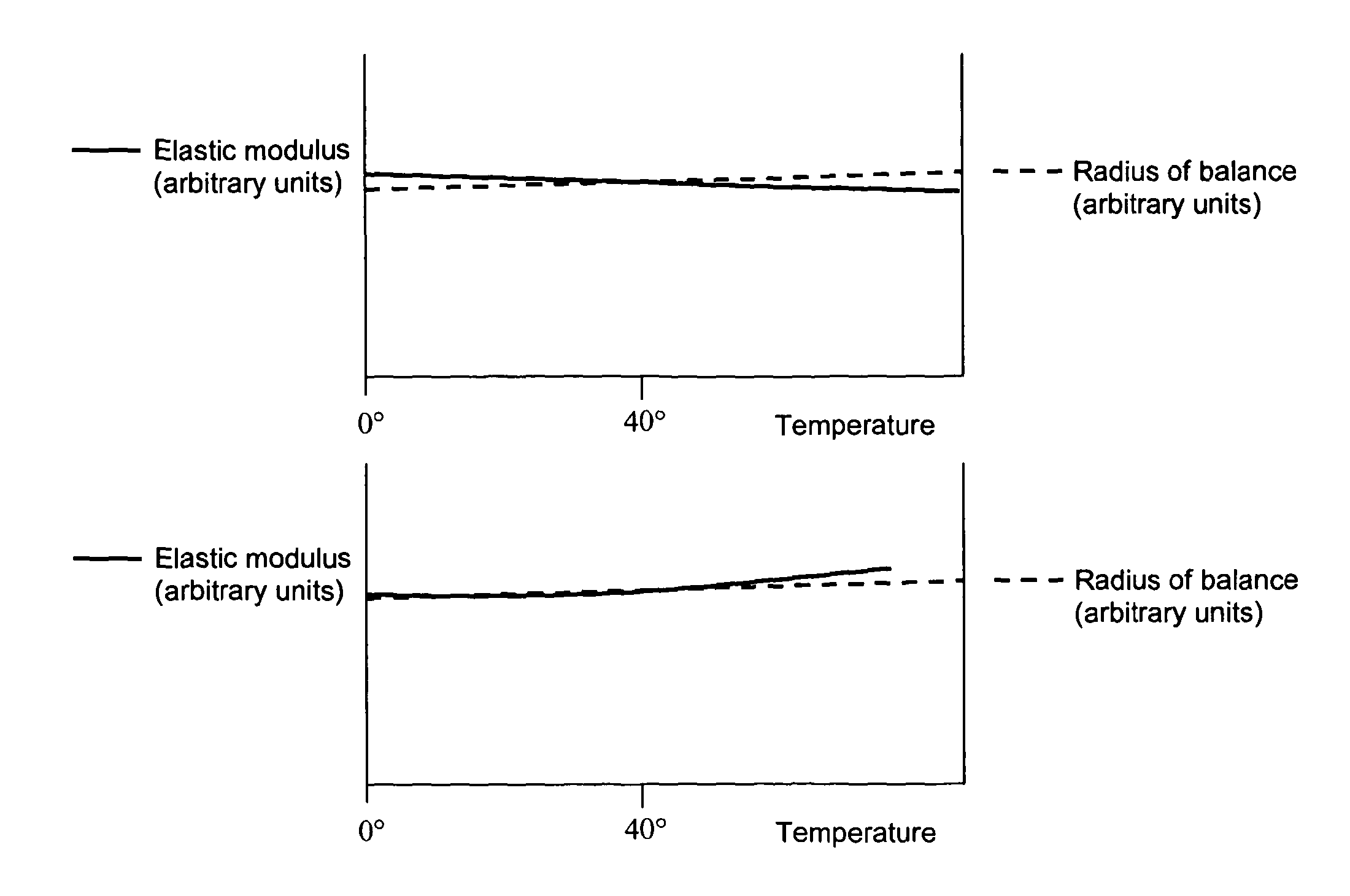
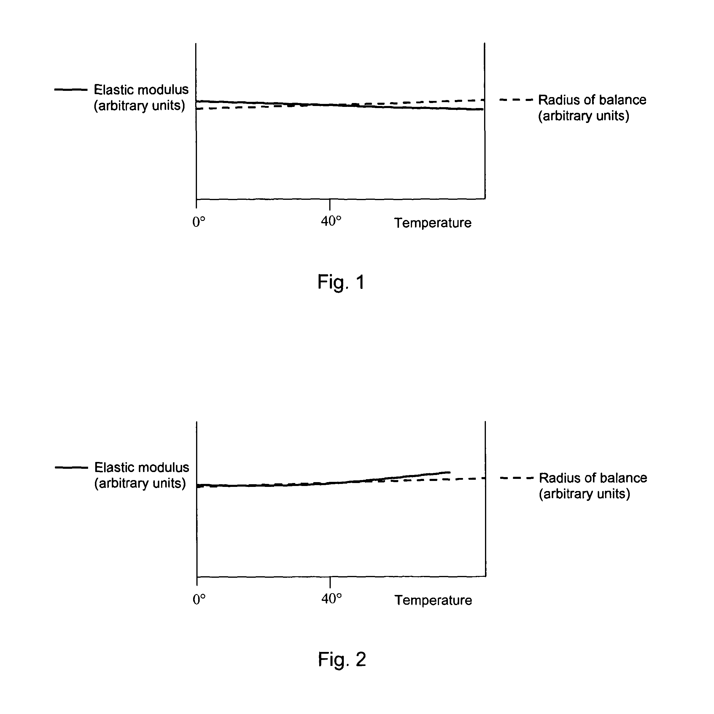
[0031]In an embodiment of the invention described below, an oscillator spring is made from a piece of amorphous (i.e. vitreous) carbon mixed with (in this case coated with) crystalline silicon dioxide.

[0032]Silicon dioxide can be both amorphous (non-crystalline) or crystalline in structure. Both structures display an abnormal (i.e. positive) thermal evolution of elastic modulus to at least 1700 K.

[0033]The amorphous carbon used in the embodiment begins as a polymer precursor. Following forming of the polymer precursor to a desired shape, the silicon dioxide is applied. However, for polymer precursor of suitable viscosity, the silicon dioxide may be intermixed before the shape-forming step is performed. In this embodiment, the proportion of silicon dioxide additive to carbon is about 4.5 mol % in the final mixture.

[0034]After the precursor (i.e. pre-phase-transformed host material) and silicon dioxide (additive) have been mixed and formed into the required shape, the mixture is heate...


PUM

PropertyMeasurementUnit
temperatureaaaaaaaaaa

Abstract

An oscillator spring material comprising a mixture of a host material with an additive in proportions which permit the thermal evolution of the material's elastic modulus to be tuned, e.g. to correct or compensate for other thermal changes in an oscillator system. The additive comprises a crystalline material having an abnormal thermal evolution of elastic modulus. The host material has a normal thermal evolution of elastic modulus. The additive is mixed with the host material before the host material undergoes a phase transformation into its final form. The additive has a phase transformation temperature higher than the host material, so that additive remains in the same state while the host material phase transformation takes place.

Description

TECHNICAL FIELD[0001]The invention relates to a material composition for controlling the thermal evolution of elastic modulus (Young's modulus) and spring stiffness of oscillator springs for precision instruments. In particular it relates to compositions for and methods of making non-magnetically sensitive springs for use in systems where thermal stability is critical to the correct functioning of the system.BACKGROUND TO THE INVENTION[0002]Up to the early twentieth century, knowledge of materials with limited coefficients of expansion was essentially limited to naturally occurring materials, elements or compounds. The advent of atomic science in the early twentieth century brought with it both an emergent understanding of materials at atomic scale and the need for measurement several magnitudes of precision greater than had previously been known. This in turn led to research for new materials, compounds or alloys, which exhibited limited thermal expansion for the purpose of buildin...

Claims


Application Information

Patent Timeline
Patent Type & Authority Patents(United States)
IPC IPC(8): B21F35/00F16F3/08B44C1/22B29C67/24F03G1/04G04B43/00F16F1/02G04B17/06F16F1/10
CPCF16F1/021G04B43/007G04B17/066F16F1/10Y10T29/49609
Inventor LEVINGSTON, GIDEON, RORY
Owner CARBONTIME
Learn More