Compressor of exhaust gas turbocharger

a technology of exhaust gas and compressor, which is applied in the field of compressor, can solve the problems of difficult to simplify the structure around, increase production cost, complicated machining work, etc., and achieve the effects of reducing production man-hours, easy adjustment, and reduced production cos

Active Publication Date: 2014-11-18
MITSUBISHI HEAVY IND LTD
View PDF15 Cites 17 Cited by
  • Summary
  • Abstract
  • Description
  • Claims
  • Application Information

AI Technical Summary

Benefits of technology

[0073]According to the above-described invention, a mating surface of the compressor housing which is divided into compressor housing members in the direction of the rotation axis of the impeller is formed in the neighborhood of an inlet part of the impeller. Hence, combining the divided compressor housing members can form the space forming the recirculation passage, the inlet slit and the outlet slit. Accordingly, the additional machining to form the inlet slit and the outlet slit can be dispensed with; and, the reduction of production man-hours as well as production cost can be achieved.
[0074]Further, the inlet slit, the outlet slit and the recirculation passage are formed around the mating surface of the compressor housing members; thus, the structure regarding the inlet slit, the outlet slit and the recirculation passage can be compactly arranged; and, the compressor housing provided with the recirculation passage can be further compact and light-weight.
[0075]Further, the inlet slit, the outlet slit and the recirculation passage are formed around the mating surface of the compressor housing members; thus, the structure and geometry of the inlet slit, the outlet slit and the recirculation passage can be easily adjusted so that the structure and geometry is suitable for enhancing the compressor performance.
[0076]Further, the recirculation passage is not opened toward the air inlet side of the impeller; thus, the noises are difficult to be transmitted the upstream side of the air flow, and the noises generated in the impeller can be reduced without a noise insulation cover.

Problems solved by technology

Thus, in the technologies of Patent Reference 1 and Patent Reference 2, there are problems that the machining work becomes complicated and the production cost is increased.
Further, according to the disclosed technologies, the machining work regarding the inlet slit has to be performed separately from the machining work regarding the outlet slit; accordingly, it becomes difficult to simplify the structure around the inlet slit, the outlet slit and the recirculation passage; further, it is also difficult to easily adjust the structure or the geometry regarding the inlet slit, the outlet slit and the recirculation passage at the same time, the structure or the geometry being suitable for the improvement of the compressor performance.

Method used


Image

  • Compressor of exhaust gas turbocharger
  • Compressor of exhaust gas turbocharger
  • Compressor of exhaust gas turbocharger

Examples


Embodiment Construction

[0094]Hereafter, the present invention will be described in detail with reference to the modes or embodiments shown in the figures. However, the dimensions, materials, shape, the relative placement and so on of a component described in these modes or embodiments shall not be construed as limiting the scope of the invention thereto, unless especially specific mention is made.

(First Mode)

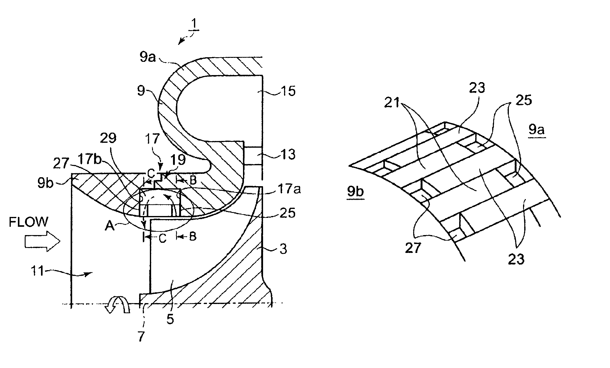
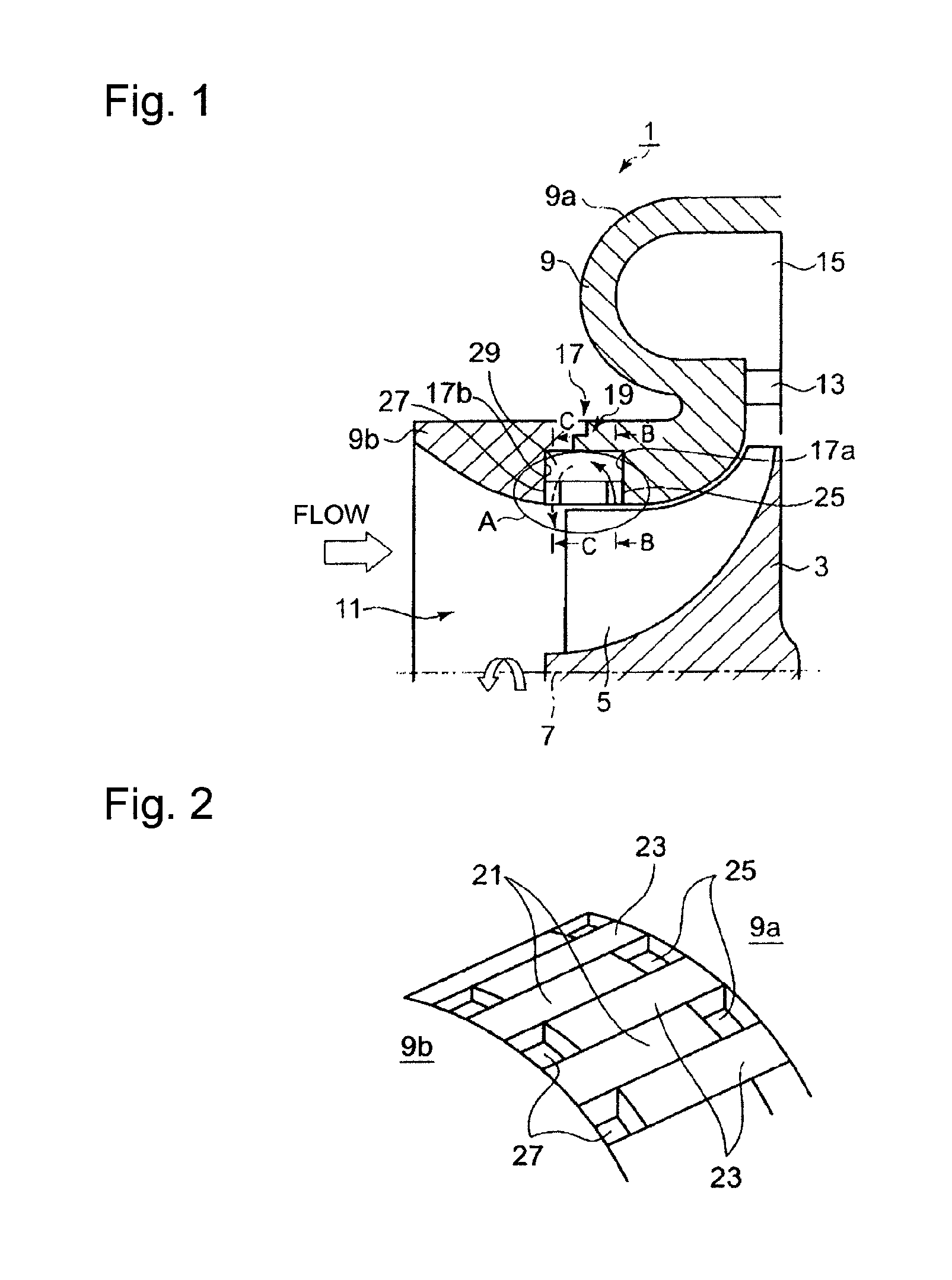
[0095]FIG. 1 shows the major parts of an exhaust gas turbocharger compressor according to a first mode of the present invention, in a cross-section that includes the rotation axis of the compressor, the major parts being depicted in an upper half plane of the cross-section divided by the rotation axis.

[0096]As shown in FIG. 1, the compressor 1 are configured so that:

[0097]an impeller 5 is fitted to the outer periphery of an end side of the rotor hub 3 whereas a turbine (not shown) is provided on another end side of the rotor hub 3; and,

[0098]the rotor hub 3 and the impeller 5 is rotated around a rotat...


PUM


Abstract

A compressor of an exhaust gas turbocharger has a compressor housing of a divided type that forms an inlet slit, an outlet slit and a recirculation passage at the same time when the compressor housing is assembled. In the compressor of the exhaust gas turbocharger, mating surfaces of compressor housing members 9a and 9b are formed in the neighborhood of the inlet part of the impeller 5 in the compressor housing 9 that is divided into the compressor housing members 9a and 9b in the direction of the rotation axis of the impeller; and, a space forming the recirculation passage 29, an inlet slit 25 and an outlet slit 27 are formed between the mating compressor housing members 9a and 9b.

Description

BACKGROUND OF THE INVENTION[0001]1. Field of the Invention[0002]The present invention relates to a compressor that is used for an exhaust gas turbocharger of an engine, the compressor including, but not limited to: a recirculation passage connecting an inlet slit that is opened toward the air passage on the casing of the impeller to an outlet slit that is opened toward the compressor inlet air passage, wherein a part of the air flow through the impeller is taken in the recirculation passage through the inlet slit whereas the air taken into the recirculation passage flows toward the compressor inlet air passage.[0003]2. Background of the Invention[0004]The compressor of the turbocharger used for a vehicle has a performance characteristic as shown in FIG. 12, in which the vertical axis and the lateral axis denote the pressure ratio of the compressor and the fluid flow rate; in FIG. 12, along a line of a constant rotation speed Ni (i=1, 2, . . . ), the smaller the flow rate, the higher...

Claims


Application Information

Patent Timeline
Patent Type & Authority Patents(United States)
IPC IPC(8): F04D29/66F04D29/68F04D29/42F04D27/02
CPCF04D29/685Y10S415/914F04D27/023F04D29/684F04D27/0238F04D29/681F04D29/682F04D29/4213F04D27/0207F04D29/624F05D2220/40F02B39/00F04D29/44F04D29/66
Inventor TOMITA, ISAOIBARAKI, SEIICHIJINNAI, YASUAKITOJO, MASAKI
Owner MITSUBISHI HEAVY IND LTD
Why Eureka
Try Eureka