Highly simplified switching regulator which allows very high switching frequencies

a switching regulator and high frequency technology, applied in the field of high-simplified switching regulators, can solve the problems of low efficiency of switching regulators, energy storage elements used in switching regulators, and efficiency reduction, and achieve the effect of increasing performance and efficiency

Inactive Publication Date: 2014-11-18
ISIK TACETTIN
View PDF25 Cites 15 Cited by
  • Summary
  • Abstract
  • Description
  • Claims
  • Application Information

AI Technical Summary

Problems solved by technology

One major drawback, however, for such regulators is their efficiency being low.
However, energy storage elements used in switching regulators have a few drawbacks.
They have undesired parasitics which causes reduction in efficiency.
They are also expensive.
Most of all, as of yet there is no feasible technique to integrate these components onto the same chip where the rest of the electronic system resides.
One problem is that complex pulse width modulation (PWM) servo mechanisms that are usually based on a sawtooth signal, cause extreme phase shift along the feedback.
As frequency increases, stabilizing such a complex system becomes cumbersome.
This would deteriorate the performance of the regulator.
Since an analog to digital converter (ADC) is required to measure the output voltage, the speed of ADC will be the limiting factor of the switching frequency.
However, such system gets even more complex and expensive.
More importantly, when a linear regulator follows a switching regulator, it is not possible to combine the linear regulator's pass transistor and the high side switch transistor in one.
The usage of a high side switch in this prior art is not continuous.

Method used


Image

  • Highly simplified switching regulator which allows very high switching frequencies
  • Highly simplified switching regulator which allows very high switching frequencies
  • Highly simplified switching regulator which allows very high switching frequencies

Examples


Embodiment Construction

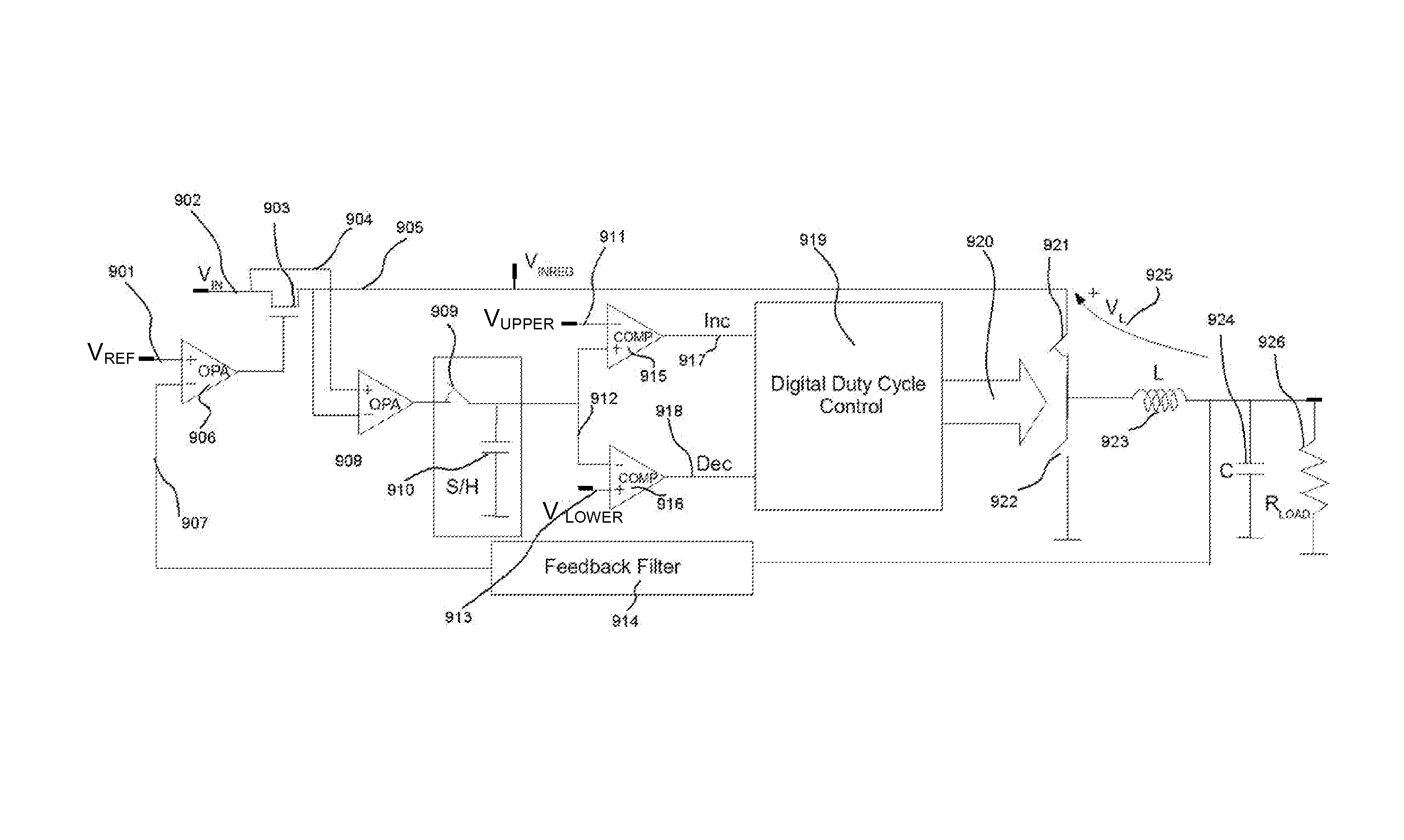
[0029]The description given here is to allow someone of ordinary skill in the art to build and use the present invention in related applications. A variety of modifications on the embodiments described, may be apparent to one skilled in the art and the general principles of the invention described here may be applicable to other embodiments. These other embodiments may be constructed using n-channel transistors instead of p-channel transistors, or vice versa; bipolar transistors instead of mos; different amplifier types instead of what is illustrated here; different digital circuits with similar functionality instead of what is suggested here; different construction topologies which functions similar to what is described here. Therefore, the scope of present invention should not be taken as limited to the particular embodiments illustrated and described herein, but given the widest scope consistent with the principal and novel features disclosed here.

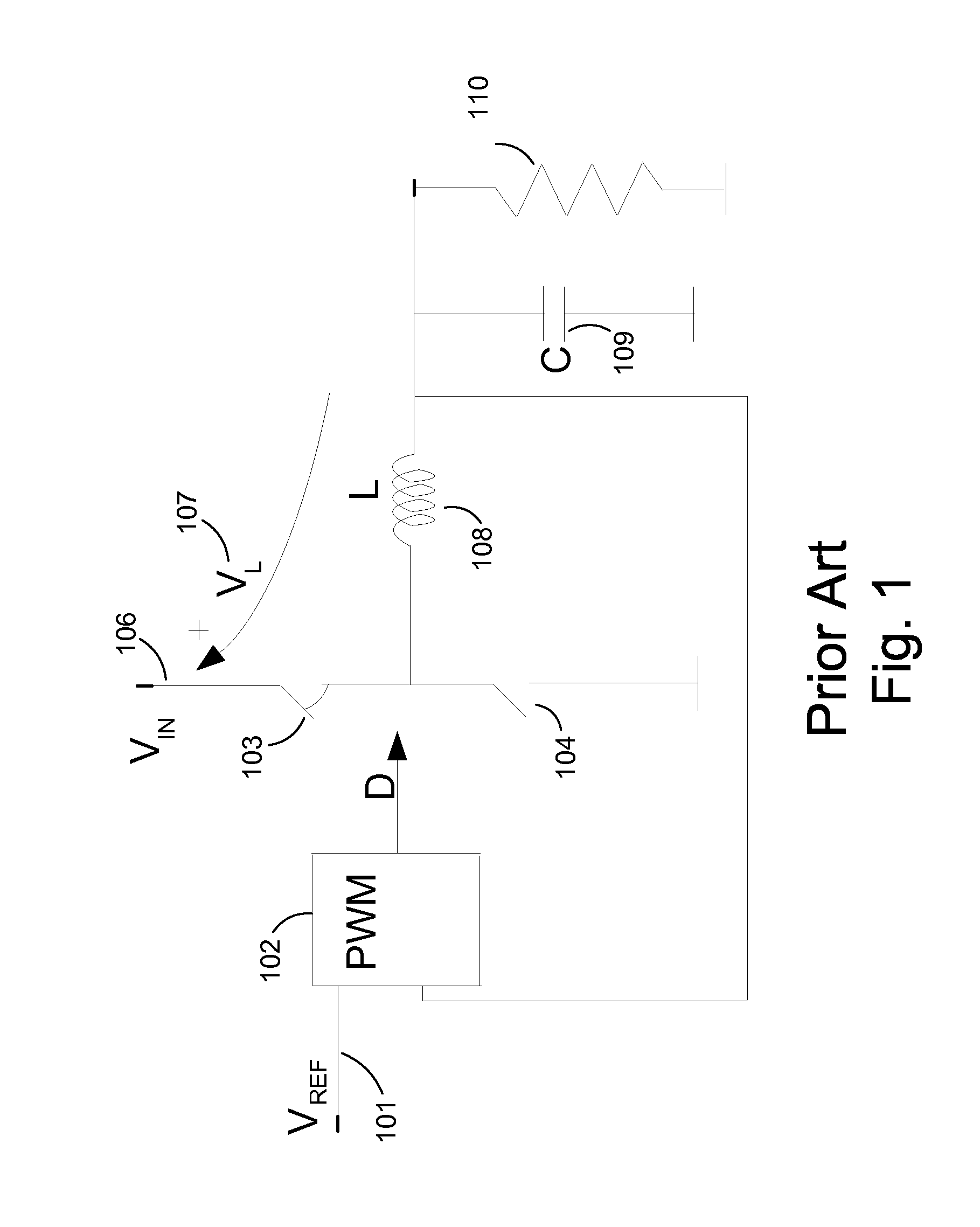
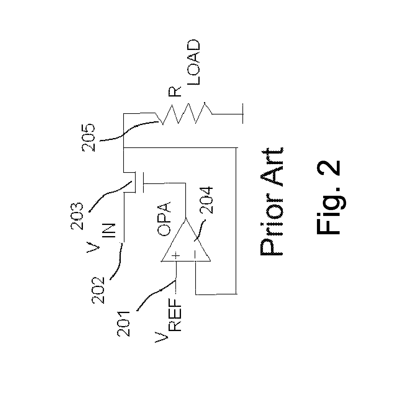
[0030]In regards to FIG. 1, a ty...


PUM


Abstract

A voltage regulator circuit includes a linear voltage regulator having a pass transistor and a first feedback from an output load, and a switching regulator having a second feedback from a voltage drop across the pass transistor. The voltage regulator further includes an efficiency monitor configured to detect the voltage drop and control predetermined steps of a duty cycle of the switching regulator based on the voltage drop.

Description

REFERENCES CITEDU.S. Patents[0001]U.S. Pat. Nos. 5,705,919, 7,084,612, 7,132,820, 20050242792, 20090261790, U.S. Pat. Nos. 5,677,558, 5,592,072, 6,150,798, 6,459,246, 6,809,504, 6,960,907, 7,230,408.Articles[0002]Isik T., James R., Power Reduction Techniques in Mixed Signal Integrated Circuits: Practical approaches, TechOnLine, Mar. 16, 2009.[0003]Hanh-Phuc Le et al., Single Inductor Switching DC-DC Converter With Five Outputs and Ordered Power—Distributive Control. IEEE JSSC, Vol. 42, NO 12, December 2007.FIELD OF THE INVENTION[0004]High efficiency power and voltage regulators.BACKGROUND OF THE INVENTION[0005]Linear low drop-out voltage regulators (LDOs) are widely used in supplying electronic systems. Their design methods are highly mature. Stability issues are resolved, and fully integrated on-chip versions are helping in the build of complex circuits on a chip without external components (U.S. Pat. No. 6,960,907). One major drawback, however, for such regulators is their efficie...

Claims


Application Information

Patent Timeline
Patent Type & Authority Patents(United States)
IPC IPC(8): H02M3/157H02M3/07H02M1/00H02M3/158
CPCH02M2001/0045H02M3/158H02M3/07Y10T307/625H02M1/0045
Inventor ISIK, TACETTIN
Owner ISIK TACETTIN
Why Eureka
Try Eureka